Efficient boost circuit for electromagnetic valve drive

A solenoid valve driving and boosting circuit technology, which is applied to valve details, valve devices, electrical components, etc., can solve problems such as complex circuit structure, low boosting efficiency, and narrow application range, achieving high speed, high reliability, Achieving Precisely Controlled Effects

Inactive Publication Date: 2012-09-19
NO 70 INST OF CHINA NORTH IND GRP
View PDF6 Cites 10 Cited by
  • Summary
  • Abstract
  • Description
  • Claims
  • Application Information

AI Technical Summary

Problems solved by technology

[0005] In order to solve the problems of complex structure, unreliable operation, low boosting efficiency and narrow application range of the traditional high-voltage generating circuit, the present invention designs a high-efficiency boosting circuit driven by a solenoid valve with superior performance, which can efficiently generate Get the set boost voltage

Method used


Image

  • Efficient boost circuit for electromagnetic valve drive
  • Efficient boost circuit for electromagnetic valve drive

Examples


Embodiment Construction

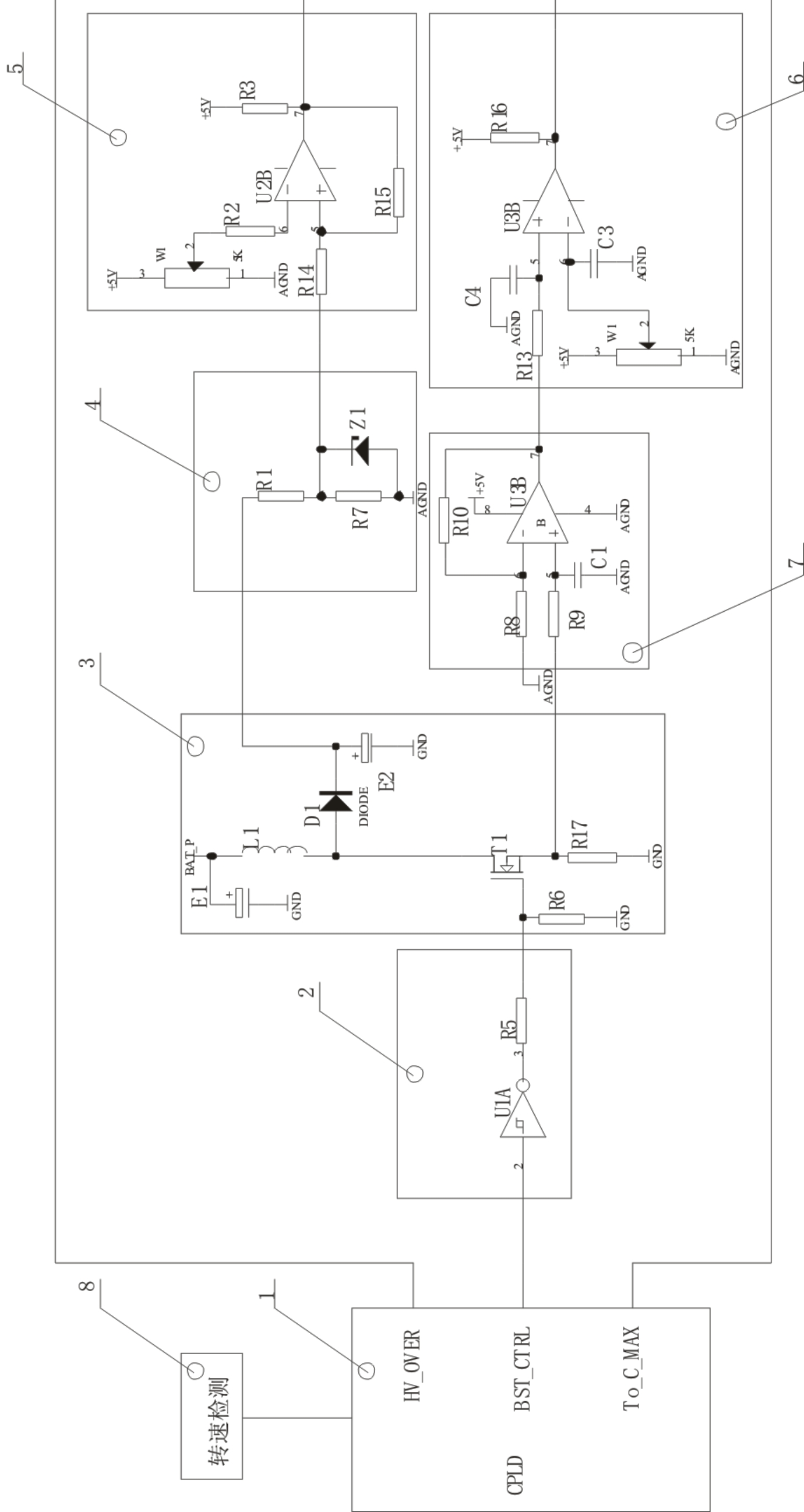
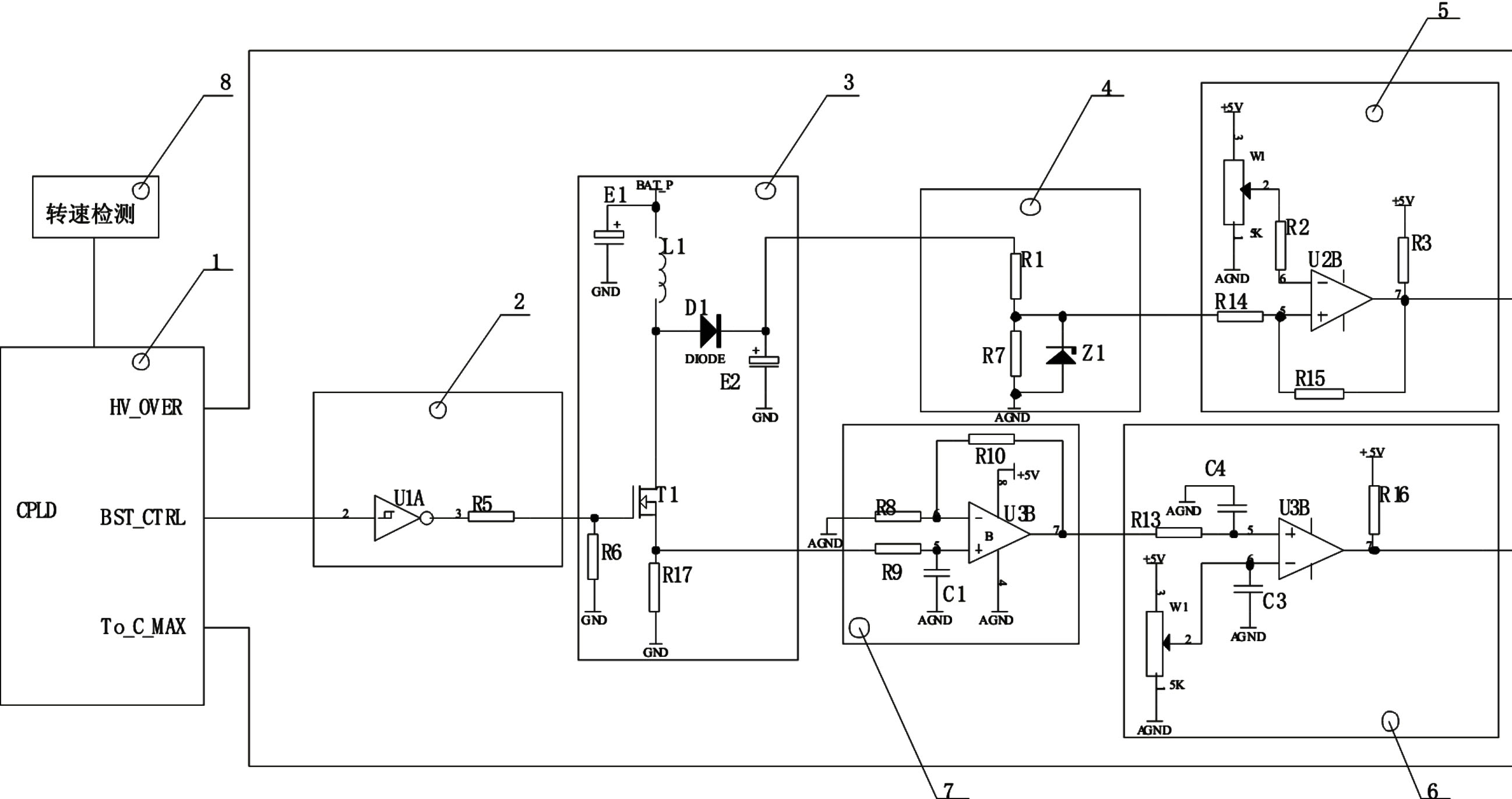
[0028] A high-efficiency boost circuit driven by a solenoid valve, the circuit is composed of a CPLD programmable logic device, a field effect transistor drive circuit, a switch circuit, a voltage detection circuit, a voltage comparator, a charging current comparator, a current amplifier, and a rotation speed detection circuit;

[0029] The CPLD programmable logic device has 4 terminals, the HV_OVER terminal is connected to the voltage comparator, the BST_CTRL terminal is connected to the field effect transistor drive circuit, the To_C_MAX terminal is connected to the charging current comparator, and the other terminal is connected to the speed detection circuit; the switch circuit has 3 Two terminals are respectively connected with the voltage detection circuit, the field effect transistor drive circuit and the current amplifier; the current amplifier is grounded;

[0030] CPLD programmable logic device, voltage comparator, voltage detection circuit, switch circuit and field e...


PUM


Abstract

The invention discloses an efficient boost circuit for electromagnetic valve drive. The circuit comprises a CPLD (Complex Programmable Logic Device) (1), a field effect transistor drive circuit (2), a switch circuit (3), a voltage detection circuit (4), a voltage comparator (5), a charge current comparator (6), a current amplifier (7) and a rotating speed detection circuit (8), wherein all the modules form two return circuits; and a dual-closed-loop feedback system is formed to realize the target of controlling connection current of a boost switch tube and the voltage of a boost capacitor. According to the invention, the boost voltage and the boost current can be conveniently and flexibly arranged through software, and the efficient boost of 100V for the electromagnetic valve drive is realized, thereby realizing the rapid drive and response capacity of an electromagnetic valve with the characteristics of high rotating speed, long oil supply duration and large current; and the efficient boost circuit for the electromagnetic valve drive is high in reliability and flexible in parameter regulation, and realizes the accurate control on the boosting current and the boosting voltage.

Description

[0001] technical field [0002] The invention belongs to the technical field of diesel engine control, and in particular relates to a high-efficiency boosting circuit driven by an electromagnetic valve. Background technique [0003] In a high-speed solenoid valve pulse width modulation and current feedback drive circuit, in order to speed up the response speed of the solenoid valve, increasing the power supply voltage of the solenoid valve is an effective method. [0004] However, the traditional high-voltage generating circuit has complex structure, unreliable operation, low boosting efficiency and narrow application range. Contents of the invention [0005] In order to solve the problems of complex structure, unreliable operation, low boosting efficiency and narrow application range of the traditional high-voltage generating circuit, the present invention designs a high-efficiency boosting circuit driven by a solenoid valve with superior performance, which can efficientl...

Claims


Application Information

Patent Timeline
Patent Type & Authority Applications(China)
IPC IPC(8): F16K31/06H02M3/155
Inventor 王孝焦玉琴褚全红孟长江白思春郭佳旭
Owner NO 70 INST OF CHINA NORTH IND GRP
Why Eureka
Try Eureka