High-temperature superconductivity knee joint radio frequency receiving coil device used for magnetic resonance imaging

A magnetic resonance imaging and high-temperature superconducting technology, applied in magnetic resonance measurement and other directions, can solve problems such as limited coils and increased use costs, and achieve the effects of improving Q value, easy operation, and preventing frostbite

Inactive Publication Date: 2012-09-19
TIME MEDICAL JIANGSU
View PDF5 Cites 4 Cited by
  • Summary
  • Abstract
  • Description
  • Claims
  • Application Information

AI Technical Summary

Problems solved by technology

During the scanning process of the magnetic resonance imaging device, in order to improve the image quality of the magnetic resonance imaging, in general, different types of coils are selected, and the coils can be designed in a specific shape to improve the signal strength. In addition, by improving the wiring form, Reduce the coupling capacitance of the overlapping parts of the coil, thereby improving the Q value of the coil. At present, most radio frequency coils are made of metal materials such as copper. The coil is limited by the copper conductor at room temperature, and is often affected by image noise associated with electronic thermal noise during the imaging process. , in order to improve the above shortcomings, the signal-to-noise ratio is often increased by extending the scan time, and the cost of use is increased

Method used


Image

  • High-temperature superconductivity knee joint radio frequency receiving coil device used for magnetic resonance imaging
  • High-temperature superconductivity knee joint radio frequency receiving coil device used for magnetic resonance imaging
  • High-temperature superconductivity knee joint radio frequency receiving coil device used for magnetic resonance imaging

Examples


Embodiment Construction

[0013] The present invention will be described in further detail below in conjunction with the accompanying drawings.

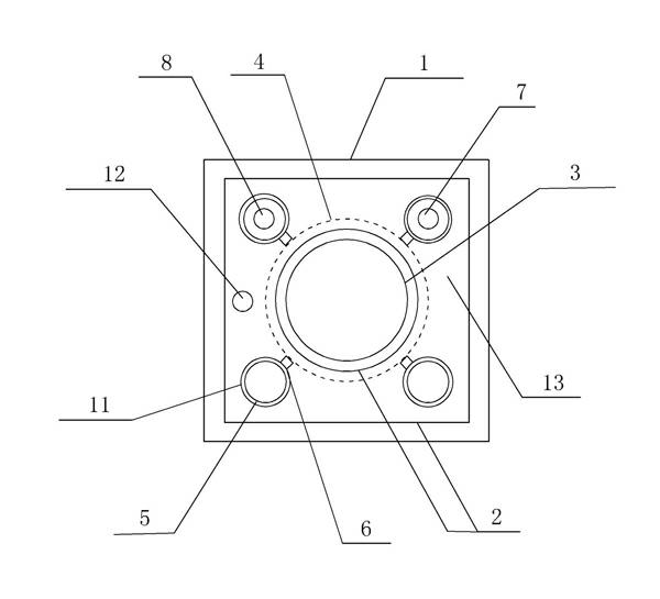
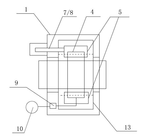
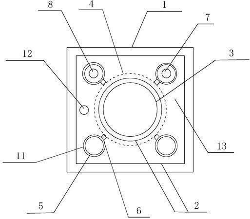
[0014] Such as figure 1 and figure 2 As shown, a high-temperature superconducting knee radio frequency receiving coil device for magnetic resonance imaging includes a housing 1, a vacuum cover 2 and a liquid nitrogen circulation system, the housing 1 is provided with a through hole 3, and the vacuum cover 2 is arranged on the housing 1 Inside, the vacuum cover 2 is provided with a vacuum outlet 12, and the vacuum cover 2 is provided with a high-temperature superconducting knee joint coil 4, and at least three liquid nitrogen tanks 5 are arranged on the periphery of the high-temperature superconducting knee joint coil 4, and the outside of the liquid nitrogen tank 5 is A thermal insulation layer 11 is provided, and the thermal insulation layer 10 is made of a non-magnetic non-metallic material, and the thermal insulation material is pearl sand; a low-tempera...


PUM


Abstract

The invention discloses a high-temperature superconductivity knee joint radio frequency receiving coil device used for magnetic resonance imaging, which comprises a shell (1), a vacuum cover (2) and a liquid nitrogen circulating system, wherein the shell (1) is provided with a through hole; the vacuum cover (2) is arranged in the shell (1); a high-temperature superconductivity knee joint coil (4) is arranged in the vacuum cover (2); the periphery of the high-temperature superconductivity knee joint coil (4) is provided with at least three liquid nitrogen tanks (5); a low-temperature heat conduction plate (6) is arranged between among the at least three liquid nitrogen tanks (5) and the high-temperature superconductivity knee joint coil (4); each liquid nitrogen tank (5) is provided with at least one liquid nitrogen liquid inlet pipe (7) and a liquid nitrogen outlet pipe (8); the lower end of the shell (1) is provided with a preamplifier (9); and one end of the preamplifier (9) is provided with a signal receiving device (10). After the above structure is adopted, the self resistance of the coil is reduced, so that a Q value of the coil is increased and an imaging signal-to-noise ratio is increased, and the signal receiving performance is improved.

Description

technical field [0001] The invention relates to a high temperature superconducting knee joint radio frequency receiving coil device, in particular to a high temperature superconducting knee joint radio frequency receiving coil device for scanning small and narrow parts such as knee joints and diagnosing objects to be measured. Background technique [0002] In the past ten years, magnetic resonance imaging technology has been widely used in medical clinical research. Since magnetic resonance imaging devices can scan and image various parts of the human body, it brings great convenience to doctors for diagnosis. During the scanning process of the magnetic resonance imaging device, in order to improve the image quality of the magnetic resonance imaging, in general, different types of coils are selected, and the coils can be designed in a specific shape to improve the signal strength. In addition, by improving the wiring form, Reduce the coupling capacitance of the overlapping p...

Claims


Application Information

Patent Timeline
Patent Type & Authority Applications(China)
IPC IPC(8): G01R33/36
Inventor 刘尊钢胡长伍钱茂飞徐臻峰高而震马启元
Owner TIME MEDICAL JIANGSU
Why Eureka
Try Eureka