Capacitor unit

A technology of capacitor units and capacitors, which is applied to multiple fixed capacitors, fixed capacitor leads, fixed capacitor shells/packages, etc. It can solve the problems of intricate connection between capacitors and devices, large lead inductance, and uneven capacitance distribution, etc., to achieve easy industrialization Mass production, easy installation and maintenance, uniform capacitance distribution effect

Active Publication Date: 2012-09-19
中信科佳信(北京)电气技术研究院有限公司
View PDF5 Cites 8 Cited by
  • Summary
  • Abstract
  • Description
  • Claims
  • Application Information

AI Technical Summary

Problems solved by technology

[0002]In the traditional inverter unit of the converter, the connection between the capacitor and the power components such as the DC bus or IGBT usually uses copper bars or bus bars. The disadvantages are:
[0003]1) Connected by copper bars or busbars, the inductance of the leads is large, and the capacitance distribution is uneven;
[0004]2) The existing capacitors use traditional power capacitors, that is, through a metal shell, two lead-out terminals are drawn on one side of the shell, and inside the shell There are multiple capacitor cores connected in series and parallel to achieve the required voltage and capacitance; the heat generated by each component in the working state cannot be effectively and quickly dissipated, resulting in the accumulation of heat in a certain part, making a certain capacitor The core causes thermal breakdown leading to failure of the entire capacitor
[0005]3) In the existing connection method, the connection between capacitors and devices is intricate and inconvenient to install, which directly affects the effective operation of electrical equipment and cannot meet the needs of the existing power electronics industry. The rapidly developing demand for the integration of various components in the

Method used


Image

  • Capacitor unit
  • Capacitor unit
  • Capacitor unit

Examples


Embodiment 1

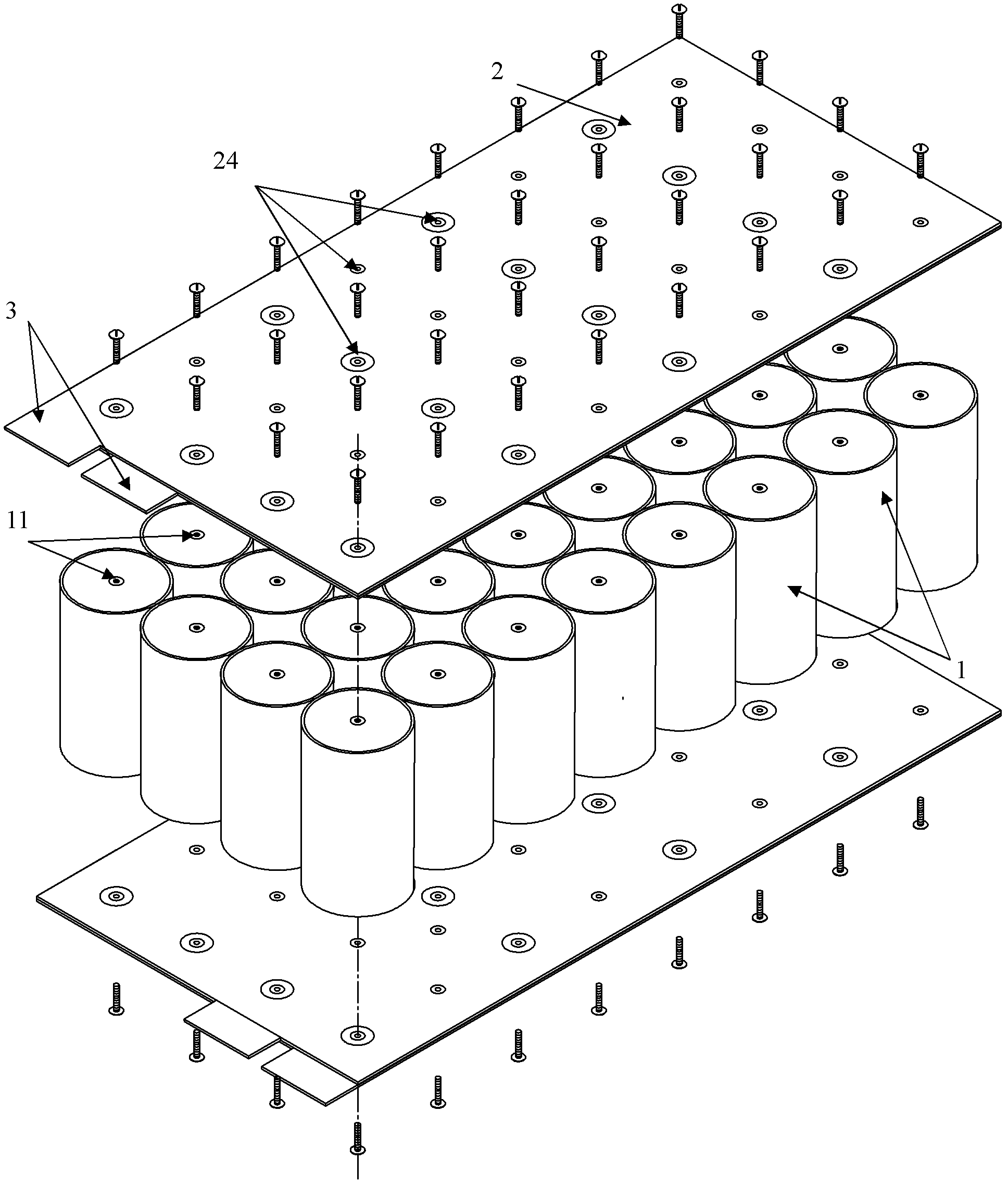
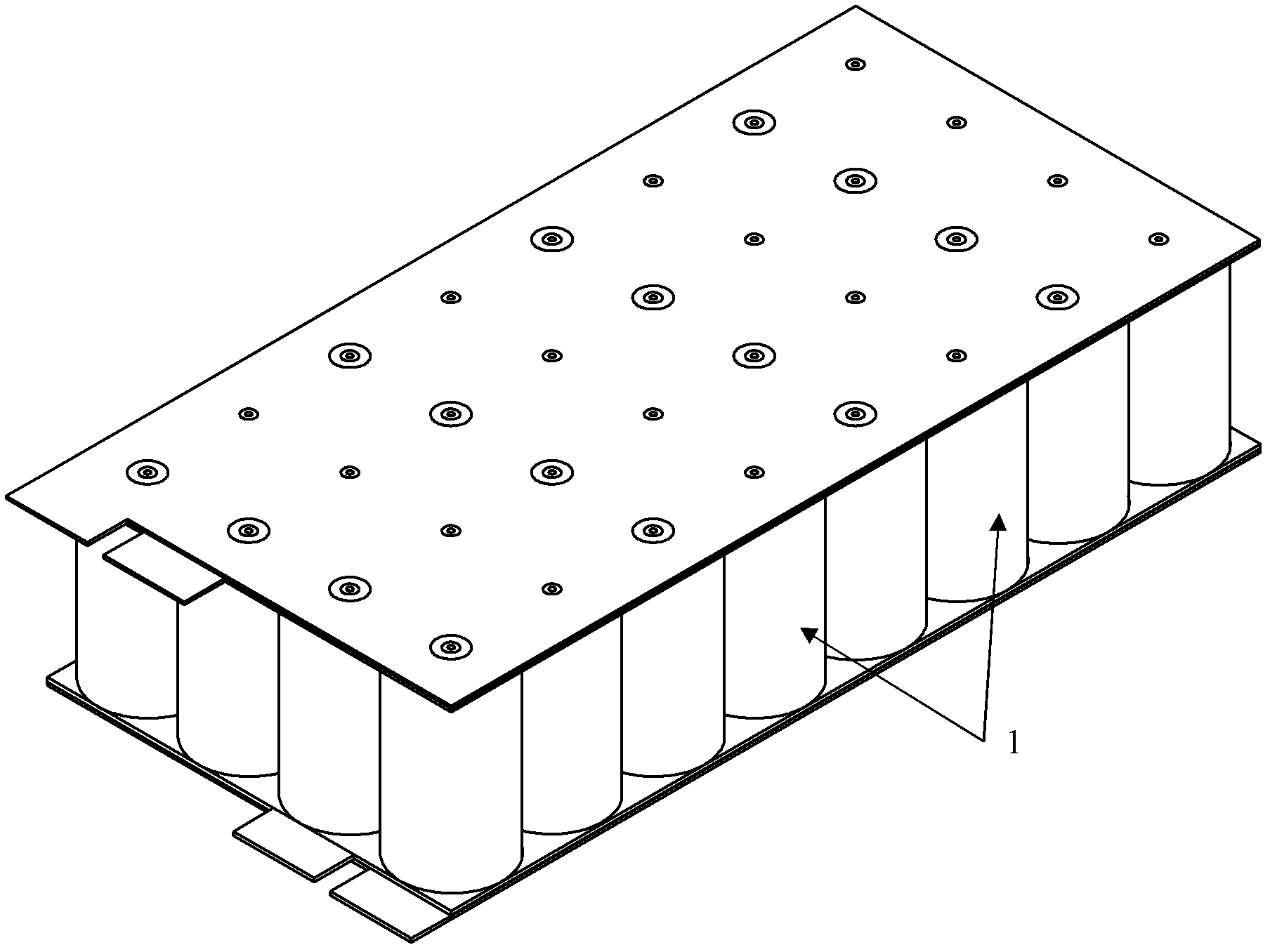
[0067] Such as Figure 1 to Figure 5 Shown, the capacitor unit of the present invention comprises:

[0068] A plurality of capacitor cells 1, all the capacitor cells are arranged in a matrix to form a capacitor array, and the electrodes 11 of each capacitor cell are bidirectionally drawn out from top to bottom;

[0069] The upper and lower composite busbars 2 cover the upper and lower sides of the capacitor array and are connected to the electrodes of each capacitor cell 1; each composite busbar is composed of upper and lower layers of metal electrodes with the same size and correspondingly arranged Plates 21, 22 are compounded, and the two layers of electrode plates are insulated from each other by an insulating layer 23; among the two layers of electrode plates 21, 22, one of the electrode plates 21 is a positive electrode plate connected to the forward current, and in addition One layer of electrode plates 22 is a negative electrode plate connected to the negative current;...

Embodiment 2

[0076] This embodiment is based on Embodiment 1, and the technical features are added on the basis of Embodiment 1. In order to save space, this embodiment only points out that the following technical features are added on the basis of Embodiment 1:

[0077] Such as Figure 7 As shown, the electrode sheet of the composite busbar and the composite busbar form an inverted L shape, and figure 1 On the basis, a terminal board 5 for connecting terminals and electrode sheets is added. The terminal board 5 is made of insulating material, arranged on the leading side of the electrode sheet 3 of the composite busbar, and installed between the electrode sheet 3 and the capacitor array;

[0078] The lead-out terminal 6 is plugged and installed on the terminal board 5 to be electrically connected with the electrode sheet 4 .

[0079] This embodiment provides a new structural form. In this structure, unified plug-in terminals are used to facilitate integrated installation and use on the c...

Embodiment 3

[0081] This embodiment is based on Embodiment 1, and some technical features have been improved on the basis of Embodiment 1. In order to save space, this embodiment only points out the differences from Embodiment 1:

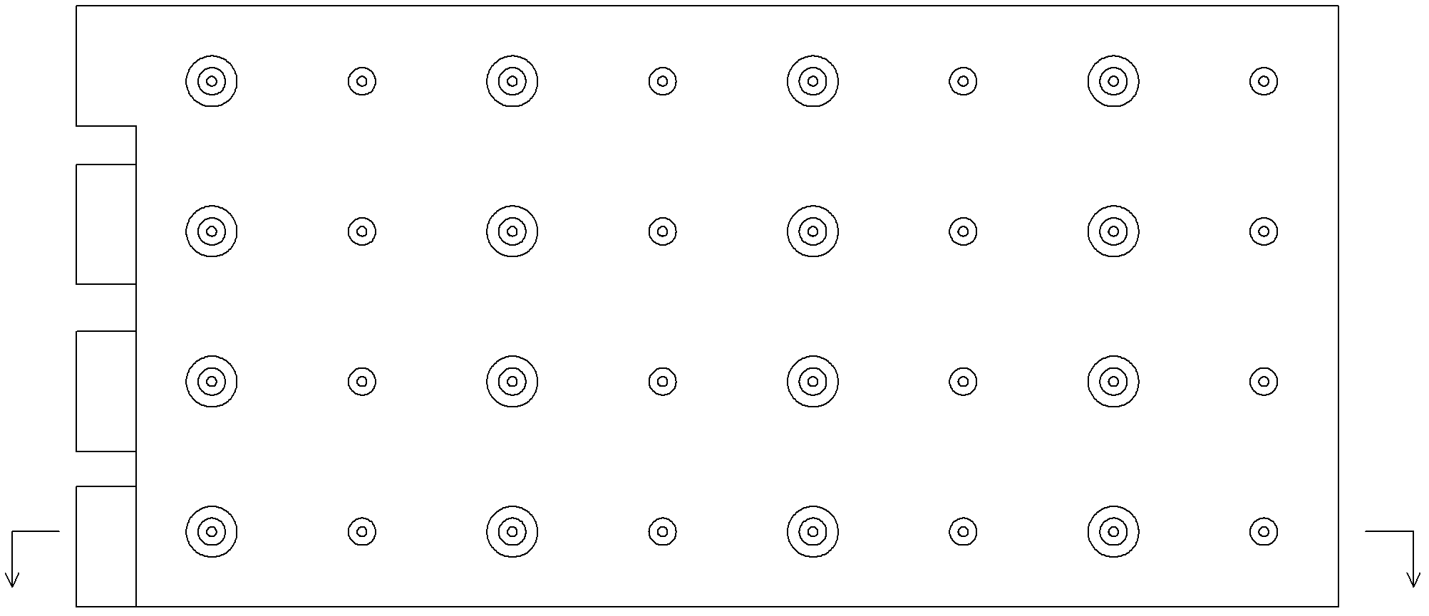
[0082] The arrangement of the capacitor cells in the first part and the capacitor cells in the second part in the capacitor array is not staggered in rows and columns but staggered with each other;

[0083] Figure 8 Shown is the arrangement of capacitor monomers connected to the upper composite busbar, where the "+" sign indicates that the corresponding capacitor is connected to the positive electrode plate end of the composite busbar, and the "-" sign indicates that the corresponding capacitor is connected to the positive electrode plate end of the composite busbar. It is the negative electrode plate end of the composite busbar.


PUM


Abstract

The invention provides a capacitor unit which is invented for solving the problems of low integration, different maintenance, large inductance and the like in the prior art. A plurality of capacitor monomers are distributed into a capacitor array, an upper composite busbar and a lower composite busbar are covered on the upper side and the lower side of the capacitor array, electrode sheets are led out on the same sides of the upper composite busbar and the lower composite busbar, a terminal board is made of insulation materials and arranged on the side where the electrode sheets are led out on the composite busbars, and an inserting lead-out terminal is installed on the terminal board and electrically connected with the electrode sheets. The capacitor unit adopts an integrated structure and is convenient to assembly, maintain and use. Lead inductance is low, capacitors are evenly distributed, and the capacitor unit can be manufactured in batch easily.

Description

technical field [0001] The invention relates to a device for an inverter unit of a converter, in particular to a capacitor unit connected to a DC bus of the inverter unit. Background technique [0002] In the traditional inverter unit of the converter, the connection between the capacitor and the power components such as the DC bus or IGBT usually uses copper bars or bus bars. The disadvantages of this method are: [0003] 1) Connected by copper bars or busbars, the inductance of the leads is large, and the capacitance is unevenly distributed; [0004] 2) The existing capacitors use traditional power capacitors, that is, through a metal shell, two lead-out terminals are drawn out on one side of the shell, and multiple capacitor cores are arranged in the shell to achieve the required The required voltage and capacitance; the heat generated by each component in the working state cannot be effectively and quickly dissipated, resulting in the accumulation of heat in a certain p...

Claims


Application Information

Patent Timeline
Patent Type & Authority Applications(China)
IPC IPC(8): H01G4/38H01G4/228H01G4/224
Inventor 贺东升郭培囵卫中科王守超付颖颖李俊梅
Owner 中信科佳信(北京)电气技术研究院有限公司
Why Eureka
Try Eureka