

Metamaterial dual-polarization radio-frequency base station antenna
A base station antenna and dual-polarization technology, applied in the field of dual-polarized radio frequency antennas, can solve the problems of versatility and performance differences
- Summary
- Abstract
- Description
- Claims
- Application Information
AI Technical Summary
Problems solved by technology
Method used
Image


Examples
Embodiment 1
[0031] Such as image 3 As shown, in this embodiment, spaces 31 and 32 for embedding inductive electronic components and / or resistors are preset on the first feeder 11 and the second feeder 12 respectively, and the preset positions for embedding electronic components in the space can be Any position on the first feeder line 11 and the second feeder line 12, and there may be more than one. Inductive electronic components can be embedded in the space 31 and the space 32 to change the inductance value on the first feeder 11 and the second feeder 12 . Using the formula: f=1 / (2π√LC), it can be seen that the inductance value is inversely proportional to the square of the operating frequency, so when the required operating frequency is a lower operating frequency, it can be realized by embedding appropriate inductance or inductive electronic components. In this embodiment, the inductance value of the added inductive electronic element ranges from 0 to 5uH. If the alternating signal ...
Embodiment 2
[0033] Such as Figure 4 As shown, in this embodiment, a space 41 and a space 42 for embedding capacitive electronic components are preset between the first feeder 11 and the metal microstructure 100, and between the second feeder 12 and the metal microstructure 100. The position embedded in the electronic component space can be any position between the first feeder 11 and the metal microstructure 100 , and between the second feeder 12 and the metal microstructure 100 . Figure 4 The middle space 41 and the space 42 are spaces for embedding capacitive electronic components in this embodiment. There is a certain capacitance between the first feeder 11, the second feeder 12 and the metal sheet 4. Here, the first feeder 11 is adjusted by embedding the capacitive electronic components. For the signal coupling between the feeder 11, the second feeder 12 and the metal sheet 4, use the formula: f=1 / (2π√LC), it can be seen that the capacitance value is inversely proportional to the sq...
Embodiment 3
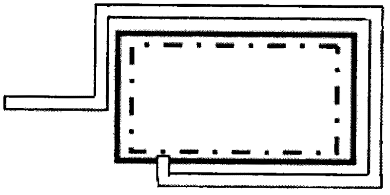
[0035] Such as Figure 5 As shown, in this embodiment, a space for embedding inductive electronic components and / or resistors is reserved on the wiring of the metal microstructure 100, and the space for embedding electronic components is not limited to the space 51 and the space shown in the figure. 52. Other positions are acceptable as long as the conditions are met. The purpose of embedding inductive electronic components here is to increase the inductance value of the internal resonant structure of the metal microstructure, thereby adjusting the resonant frequency and operating bandwidth of the antenna; same as the first embodiment, the purpose of embedding resistors here is to improve the antenna radiation resistance. As for embedding inductive electronic components or resistors, it depends on the needs. In addition, wires are used to short-circuit in the space where electronic components are not embedded.
PUM
 Abstract
Description
Claims
Application Information