Supercharge Your Innovation With Domain-Expert AI Agents!

Integrated gasification combined cycle system with vapor absorption chilling

一种循环系统、整体气化的技术,应用在整体气化联合循环系统领域,能够解决低总体功率设备净输出和效率、成本高昂、不切实际等问题

Active Publication Date: 2012-09-26
AIR PROD & CHEM INC
View PDF5 Cites 0 Cited by
  • Summary
  • Abstract
  • Description
  • Claims
  • Application Information

AI Technical Summary

Problems solved by technology

Therefore, this type of parasitic load results in lower overall power device net output and efficiency
Also, using cooling tower water to cool CO2 compressors may be cost-prohibitive and impractical in areas where water may be expensive and / or scarce

Method used


Image

  • Integrated gasification combined cycle system with vapor absorption chilling
  • Integrated gasification combined cycle system with vapor absorption chilling
  • Integrated gasification combined cycle system with vapor absorption chilling

Examples


Embodiment Construction

[0061] Referring now to the drawings, like numerals in the drawings represent like elements throughout the various views.

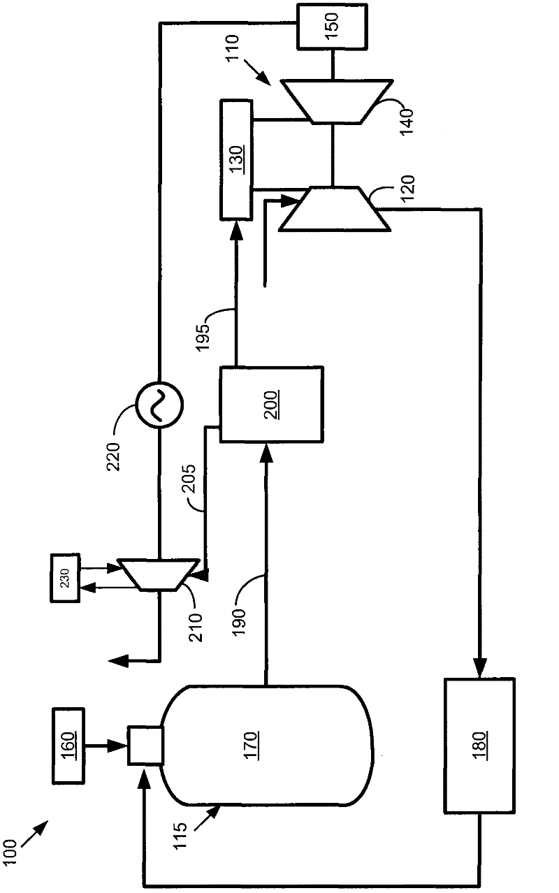
[0062] pieces, figure 1 A schematic diagram of a known integrated gasification combined cycle system 100 is shown. For simplicity, only those elements relevant to the subject matter described herein are shown. The overall integrated gasification combined cycle system 100 may have many other configurations and use many other types of equipment.

[0063] Integrated gasification combined cycle system 100 may include one or more gas turbine engines 110 . As is known, gas turbine engine 110 may include compressor 120 for compressing an incoming airflow. Compressor 120 delivers a stream of compressed air to combustor 130 . Combustor 130 mixes the compressed air flow with the compressed fuel flow and ignites the mixture. Although only a single combustor 130 is shown, the gas turbine engine 110 may include any number of combustors 130 . In turn, the hot com...


PUM


Abstract

The invention relates to an integrated gasification combined cycle system with vapor absorption chilling. The present application and the resultant patent provide an integrated gasification combined cycle system (100). The integrated gasification combined cycle system (100) may include a gas turbine engine (110), one or more power plant components (335), one or more carbon dioxide compressors (210), and a vapor absorption chiller (240). The vapor absorption chiller (240) is driven by a waste heat source flow (270) from the carbon dioxide compressors (210) to produce a chilling medium flow (300) to cool the power plant components (335).

Description

technical field [0001] The present application relates generally to integrated gasification combined cycle systems, and more particularly to integrated gasification combined cycle systems using vapor absorption quenching driven by waste heat from a gas compression system. Background technique [0002] In general, carbon dioxide (“CO2”) produced in power generating equipment 2 ”) is considered a greenhouse gas. Therefore, carbon dioxide produced during the overall power generation process is typically sequestered and then recycled for other purposes or otherwise disposed of. In the current Integrated Gasification Combined Cycle (“IGCC”) In the system, pre-combustion capture of carbon dioxide is preferred. Once captured, the carbon dioxide can usually undergo compression prior to transport, disposal, or other use. Specifically, various integrated gasification combined cycle system designs require that the gas be recirculated to Carbon dioxide is compressed prior to, for examp...

Claims


Application Information

Patent Timeline
Patent Type & Authority Applications(China)
IPC IPC(8): F02C6/00F02C7/12C10J3/00F25B15/10
CPCY02E20/185F02C7/143Y02B30/625C10J3/466F25B27/02C10J3/00F25B15/00Y02E20/18Y02E20/16F01K23/067F25B15/02F02C3/28F01K23/068C10J2300/1678C10J2300/1653Y02E20/32Y02P20/10Y02P20/129Y02P80/15Y02A30/274
Inventor B·佩米A·K·沙马R·萨哈I·马宗德Q·周C·M·罗宾斯P·R·斯卡博罗A·V·德里斯科尔
Owner AIR PROD & CHEM INC
Features
  • R&D
  • Intellectual Property
  • Life Sciences
  • Materials
  • Tech Scout
  • Unparalleled Data Quality
  • Higher Quality Content
  • 60% Fewer Hallucinations
Learn More