
Particle capture unit, method for manufacturing the same, and substrate processing apparatus

A substrate processing device and particle capture technology, applied in the direction of reacting gas medium and gas medium, manufacturing tools, chemical instruments and methods, etc., can solve the damage of TMP rotor blades, reduce exhaust efficiency, and reduce exhaust efficiency and other problems, to achieve reliable capture, prevent foreign matter from entering the treatment chamber, and prevent damage

Inactive Publication Date: 2012-09-26
TOKYO ELECTRON LTD
View PDF5 Cites 8 Cited by
  • Summary
  • Abstract
  • Description
  • Claims
  • Application Information

AI Technical Summary

Problems solved by technology

[0007] However, since the reflector according to the above-mentioned Patent Document 1 is arranged so as to shield the inside of the exhaust pipe, the conductance of the exhaust flow path is lowered, thereby reducing the exhaust efficiency.
In addition, although the capture mechanism related to Patent Document 1 is arranged along the inner surface of the exhaust pipe, in order to capture the particles that have entered the capture mechanism, the kinetic energy is lost because the particles that have entered repeatedly collide with the components of the capture mechanism. The required specified thickness is very necessary. As a result, since the capture mechanism protrudes into the exhaust pipe, the conductivity of the exhaust flow path will still be reduced and the exhaust efficiency will be reduced.
If the exhaust efficiency is reduced, it will take time to evacuate the chamber, and the operating rate of the substrate processing equipment will decrease.
[0008] And, although the above-mentioned patent document 1 discloses the situation of using a cotton-like body made of fibers as a constituent material of the catching mechanism, the following problem also occurs: the fiber is easy to fall off from the cotton-like body, and when the fallen fiber If a part falls to the TMP, it may damage the rotor blade of the TMP

Method used


Image

  • Particle capture unit, method for manufacturing the same, and substrate processing apparatus
  • Particle capture unit, method for manufacturing the same, and substrate processing apparatus
  • Particle capture unit, method for manufacturing the same, and substrate processing apparatus

Examples


Embodiment Construction

[0033] Hereinafter, embodiments of the present invention will be described with reference to the drawings.

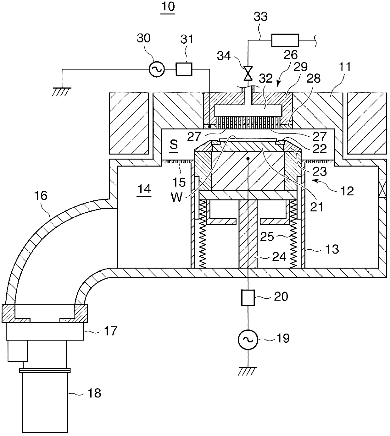
[0034] figure 1 It is a cross-sectional view schematically showing the structure of a substrate processing apparatus to which the particle trap unit according to the embodiment of the present invention is applied.

[0035] exist figure 1 Among them, as a substrate processing apparatus 10 configured as an etching processing apparatus for performing reactive ion etching (Reactive Ion Etching) (hereinafter referred to as “RIE”) on a semiconductor wafer (hereinafter, simply referred to as “wafer”) W, it is equipped with metal, The chamber 11 (processing chamber) is formed of, for example, aluminum or stainless steel and has a shape in which two large and small cylinders overlap.

[0036] Arranged in the chamber 11 are: a lower electrode 12 serving as a wafer stage on which a wafer W is placed and ascending and descending in the chamber 11 together with the placed wafer W;...


PUM


Abstract

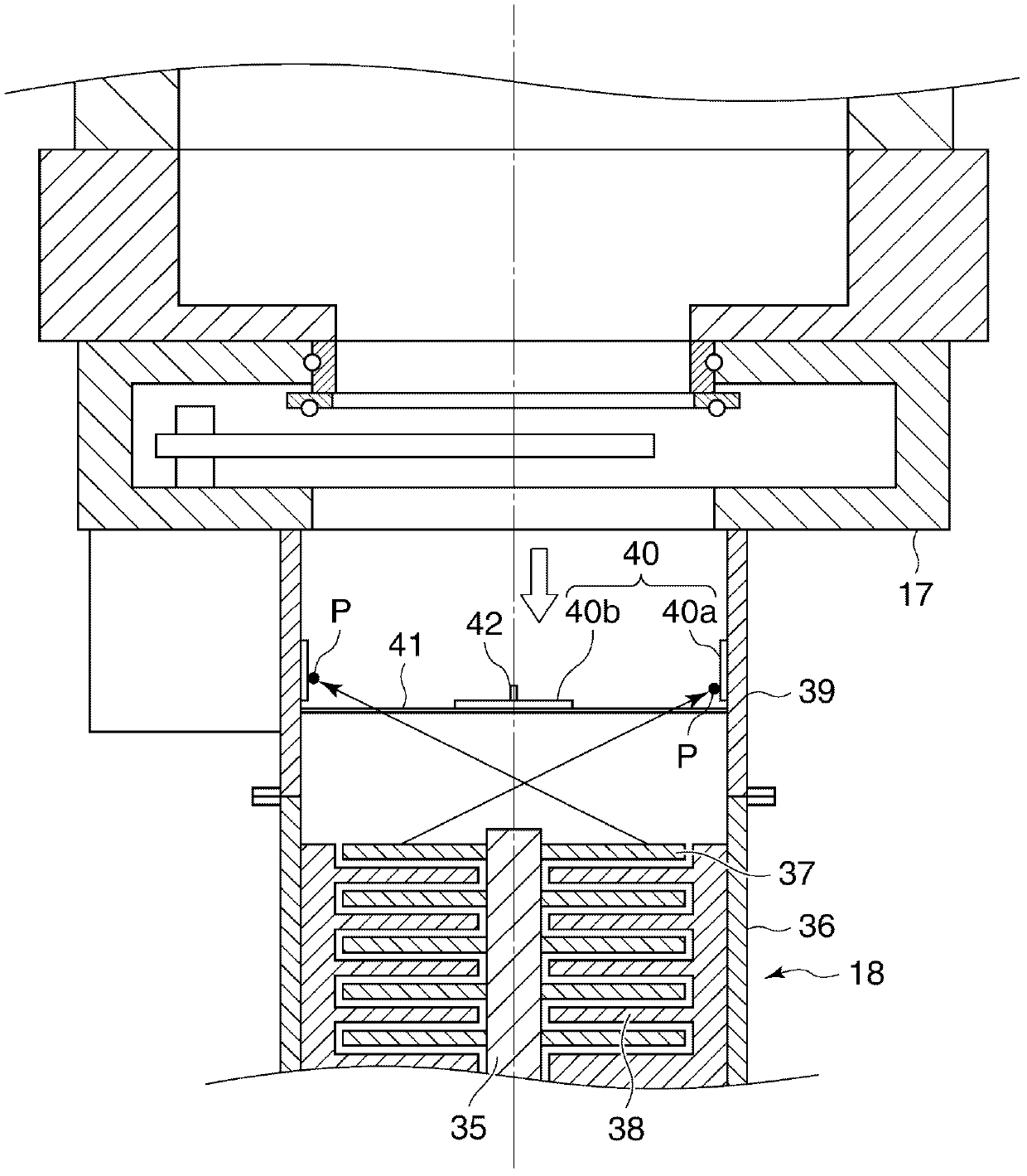
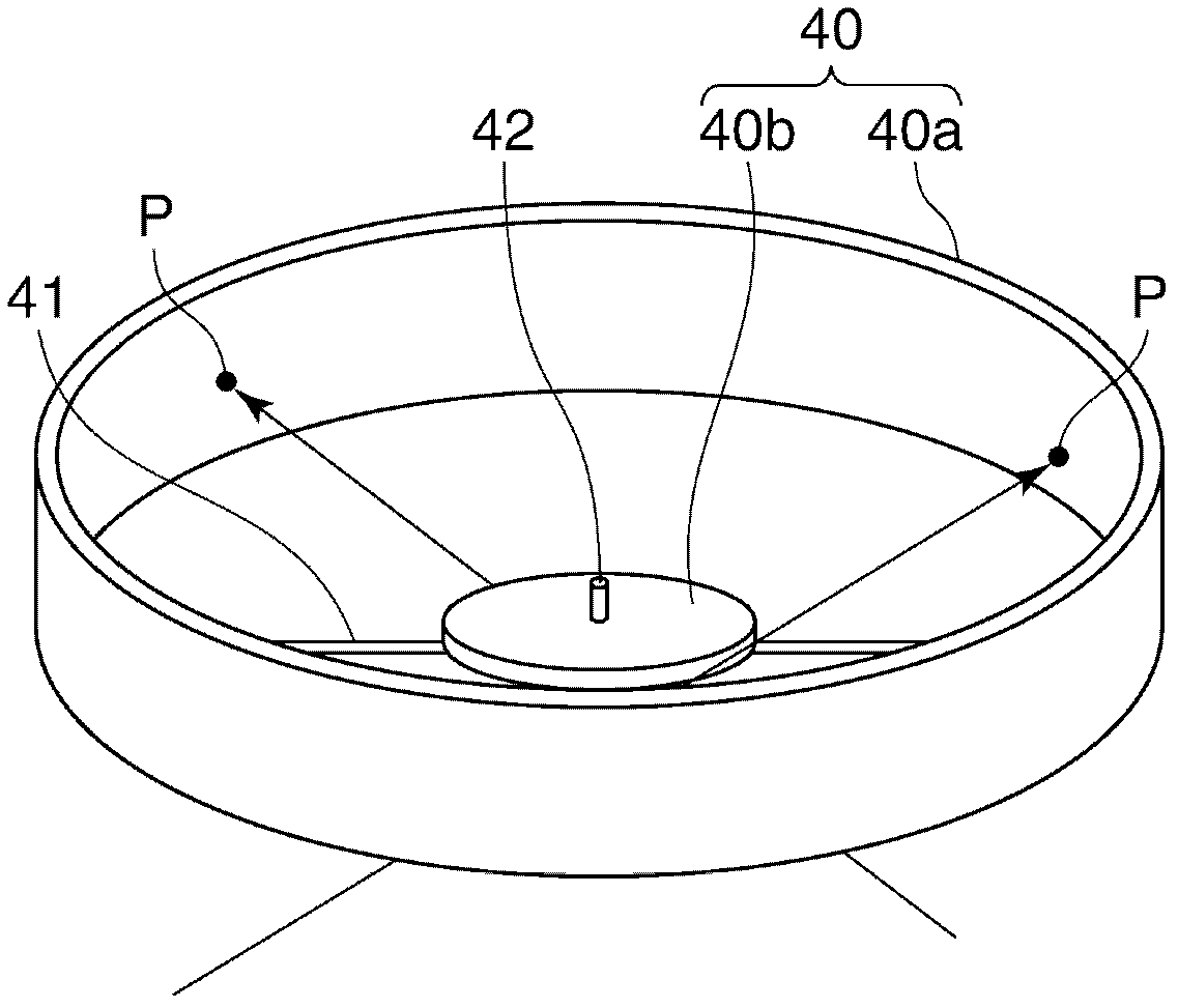
The present invention provides a particle capture unit which is capable of preventing deterioration of exhaust efficiency. The particle capture unit adopted to be exposed to a space in which particles fly includes at least a first reticular layer formed of a plurality of first fiber-like materials and a second reticular layer formed of a plurality of second fiber-like materials. The first fiber-like materials are thinner than the second fiber-like materials and arrangement density of the first fiber-like materials in the first reticular layer is higher than that of the second fiber-like materials in the second reticular layer, the second reticular layer is interposed between the first reticular layer and the space, and the first and second reticular layers are hardened and bonded together by sintering.

Description

technical field [0001] The present invention relates to a particle trapping unit for trapping unnecessary particles moving in a substrate processing apparatus, a method of manufacturing the particle trapping unit, and a substrate processing apparatus. Background technique [0002] Generally, a substrate processing apparatus for performing predetermined processing on substrates such as wafers for semiconductor devices, FPD panels such as liquid crystals, glass substrates such as solar cells, etc., includes a processing chamber for accommodating the substrates and performing predetermined processing (hereinafter referred to as "chamber"). In this chamber, fine particles caused by deposits on the inner wall of the chamber or reaction products generated in predetermined processes float. When these floating particles adhere to the surface of the wafer, a wiring short circuit occurs in a product manufactured from the wafer, for example, a semiconductor device, thereby reducing th...

Claims


Application Information

Patent Timeline
Patent Type & Authority Applications(China)
IPC IPC(8): H01L21/3065F04D19/04
CPCH01L21/00Y10S55/05Y10S264/48Y10S29/902F04B37/08F04D19/042Y10T29/49316Y10T156/1043F04D19/04F04D29/701H01L21/02
Inventor 守屋刚丰泉俊介高广克之
Owner TOKYO ELECTRON LTD
Learn More