Numerical control equipment

A numerical control equipment and combined technology, applied in metal processing equipment, large fixed members, driving devices, etc., can solve the problems of affecting accuracy, poor movement, inaccurate positioning, etc., and achieve the effect of improving the overall rigidity

Inactive Publication Date: 2012-10-03
杨东佐
View PDF9 Cites 28 Cited by
  • Summary
  • Abstract
  • Description
  • Claims
  • Application Information

AI Technical Summary

Problems solved by technology

In the moving column type CNC machining center of this invention, since the longitudinal column on which the main shaft is installed is only supported on one side, the main shaft has poor stability, inaccurate positioning, poor movement and too fast movement during movement.
[0006] There is also an existing numerical control equipment, one end of the X screw rod is installed on the main frame, and the other end is installed on the X slide seat. On the one hand, the movement of the X-direction screw rod of this numerical control equipment is easy to interfere with the movement of the Y-direction slide seat. , on the other hand, the X-direction screw will swing a little with the movement of the X slide, which will greatly affect the accuracy

Method used


Image

  • Numerical control equipment
  • Numerical control equipment
  • Numerical control equipment

Examples


Embodiment 2

[0096] Such as Figure 5 to Figure 7 As shown, the difference from Embodiment 1 is that the Y-slider 70 includes a Y-slider base plate 71, and the upper convex portion 72 protrudes vertically upward from the Y-slider base plate 71, and vertically extends from the Y-slider base plate 71. The lower convex part 73 is convexly provided. A fixing plane 74 is provided on the outer surfaces of the upper protrusion 72 and the lower protrusion 73 , and a side protrusion 75 is provided on the fixing plane 74 . The outer periphery of the bottom plate 71 of the Y-direction sliding seat is square, and an upper convex portion 72 and a lower convex portion 73 protrude from the periphery. A round hole 78 and a square hole 79 are provided in the Y-direction sliding seat 70 through the upper convex part 72, the Y-direction sliding seat bottom plate 71, and the lower convex part 73. The round hole 78 is placed in the center of the square hole 79, and the round hole 78 The diameter is greater t...

Embodiment 3

[0099] Such as Figure 8 As shown, the difference from Embodiment 2 is that the Y-slider 120 includes a Y-slider bottom plate 121, a circular tube-shaped upper guide sleeve 122 protruding vertically upward from the Y-slider bottom plate 121, and a Y-slider bottom plate 121 protrudes vertically downwards to the circular tube-shaped lower guide sleeve 123, the outer periphery of the Y-slide base plate 121 is a square, and the periphery protrudes from the circular tube-shaped upper guide sleeve 122 and the circular tube-shaped lower guide sleeve 123.

[0100]The spindle device comprises a cylindrical Z guide rod 126 that can move up and down, an end cover 127, a rotating shaft 128 that is installed in the Z guide rod 126 and can only rotate relative to the Z guide rod 126, a bearing 132, a bearing 131, an externally threaded nut 134, and a drive The rotating shaft 128 rotates the first rotor 129 and the first stator 130 , the internally threaded nut 135 , the Z-direction driving ...

Embodiment 4

[0102] Such as Figure 9 As shown, the difference from Embodiment 1 is that the X forward guide rail and the X backward guide rail are sliding guide rails, including a cylindrical X guide shaft 200, an X guide shaft support 201, and an X guide guide sleeve sliding seat 202. The shaft support 201 is provided with an arc surface 204 that cooperates with the X guide shaft 200. The X guide shaft 200 is installed on the X guide shaft support 201 and fits with the arc surface 204 on the X guide shaft support 201. The X guide shaft support 201 is fixed on the X-direction rail support part 205, and the X-direction rail sleeve slide seat 202 is fixed on the bottom of the side protrusions 207 on the front and rear sides of the X-direction slide seat 206. The X-guiding guide sleeve sliding seat 202 cooperates with the X-guiding shaft 200 and the X-guiding shaft bracket 201 installed together.

[0103] Y guide rail to the left and Y guide rail to the right are sliding guide rails, includ...


PUM


Abstract

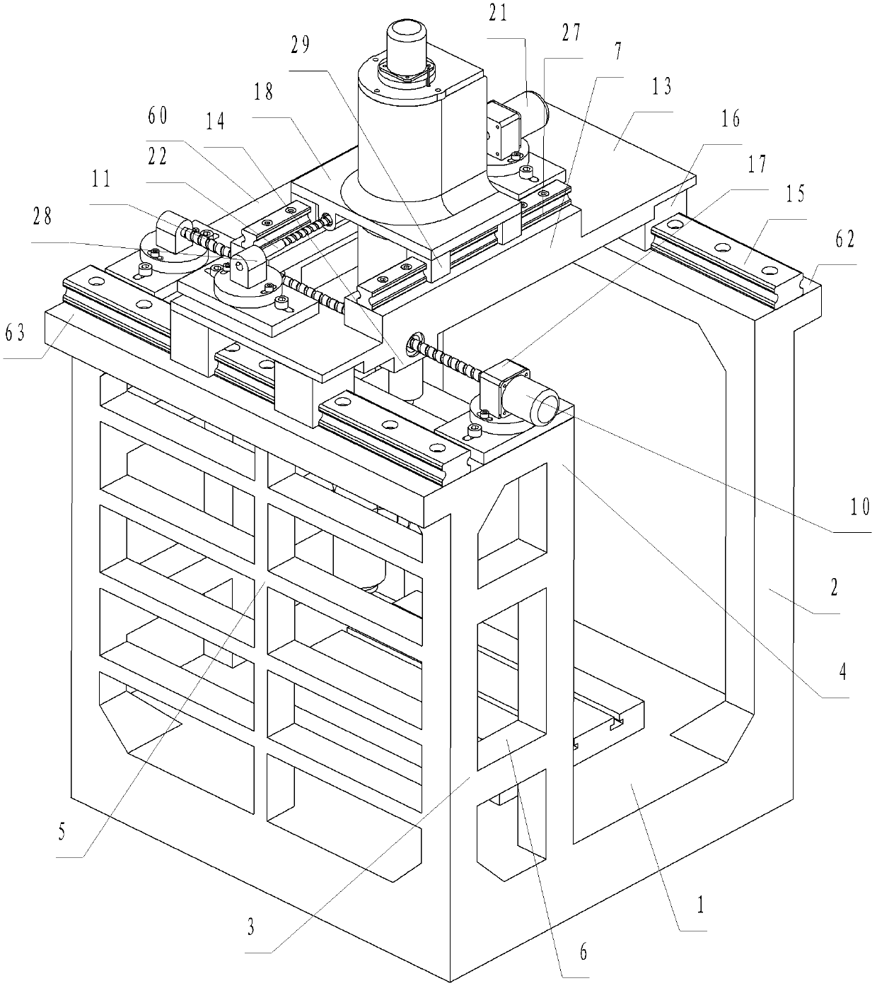
Numerical control equipment comprises a main frame and a workpiece clamping device. The main frame consists of a base, a first main support portion and a second main support portion, and the first main support portion and the second main support portion are arranged on two opposite sides of the base and are mounted with the base. The numerical control equipment is characterized in that the first main support portion and the second main support portion consist of separate first sides on the middle upper portions, a first driving device and a first driving device mounting portion, the first driving device drives an X-direction sliding seat to reciprocate, the first driving device mounting portion is connected with the first main support portion or the second support portion and is placed between an X-direction front guide rail and an X-direction rear guide rail, and the first driving device consists of an X-direction lead screw or a group of X-direction linear motors which drives the X-direction sliding seat to reciprocate and is parallel to the X-direction front guide rail and the X-direction rear guide rail. The X-direction lead screw penetrates through the X-direction sliding seat, and two ends of the X-direction lead screw are protruded out of a worktable and mounted on the first driving device mounting portion; or two ends of a stator of each X-direction linear motor are protruded out of the worktable and are fixed to the first driving device mounting portion. The numerical control equipment has the advantage that a workpiece is convenient to hoist.

Description

technical field [0001] The present invention relates to a numerical control equipment, in particular to a main processing head numerical control machine tool, numerical control painting equipment, numerical control welding equipment, numerical control laser cutting equipment, numerical control laser welding equipment, numerical control plasma cutting equipment, numerical control screw mounting equipment, numerical control gas cutting equipment Wait. Background technique [0002] Existing numerical control equipment, one is workbench movement. For example, in the invention patent with the application number of 201010284237.9, a CNC gantry vertical compound machine tool is disclosed, including a base, a workbench, and a column. The column is movably connected by a column guide rail or fixedly connected with a composite beam through a fastener. The composite beam passes through the beam. There are more than two sliding saddles that are movably connected or fixedly connected by...

Claims


Application Information

Patent Timeline
Patent Type & Authority Applications(China)
IPC IPC(8): B23Q37/00B23Q5/40B23Q1/01
CPCB23Q5/28B23Q1/015B23Q5/02B23Q1/0009B23Q5/40B23Q1/01B23Q1/012B23Q5/36
Inventor 杨东佐
Owner 杨东佐
Why Eureka
Try Eureka