
Feeding equipment of biomass gasification furnace

A technology of feeding equipment and gasifier, which is applied in the direction of gasification of granular/powdered fuel, educts, and production of combustible gas. Ingenious and reasonable, to ensure the effect of clean environment and stable pressure

Active Publication Date: 2014-03-26
无锡湖光工业炉有限公司
View PDF9 Cites 0 Cited by
  • Summary
  • Abstract
  • Description
  • Claims
  • Application Information

AI Technical Summary

Problems solved by technology

[0004] However, the current biomass gasifier is still in its infancy. Some small gasifiers are easy to block pipes and switches with tar when they are in use, and emit peculiar smell when using them. The waste residue and tar water are dumped randomly, causing secondary pollution
At present, the large gasifiers on the market need to be shut down when charging, and cannot work continuously. This is because the upper cover of the gasifier needs to be opened for the second charging. At this time, there is still a large amount of gas in the furnace, and the temperature is at Above 300°C, the high-temperature gas is combined with oxygen in the air under pressure, and it is easy to explode. When the worker opens the furnace cover, the CO concentration in the furnace body is 20%, and accidents are prone to occur

Method used


Image

  • Feeding equipment of biomass gasification furnace
  • Feeding equipment of biomass gasification furnace
  • Feeding equipment of biomass gasification furnace

Examples


Embodiment Construction

[0024] The present invention will be further described below in conjunction with specific drawings and embodiments.

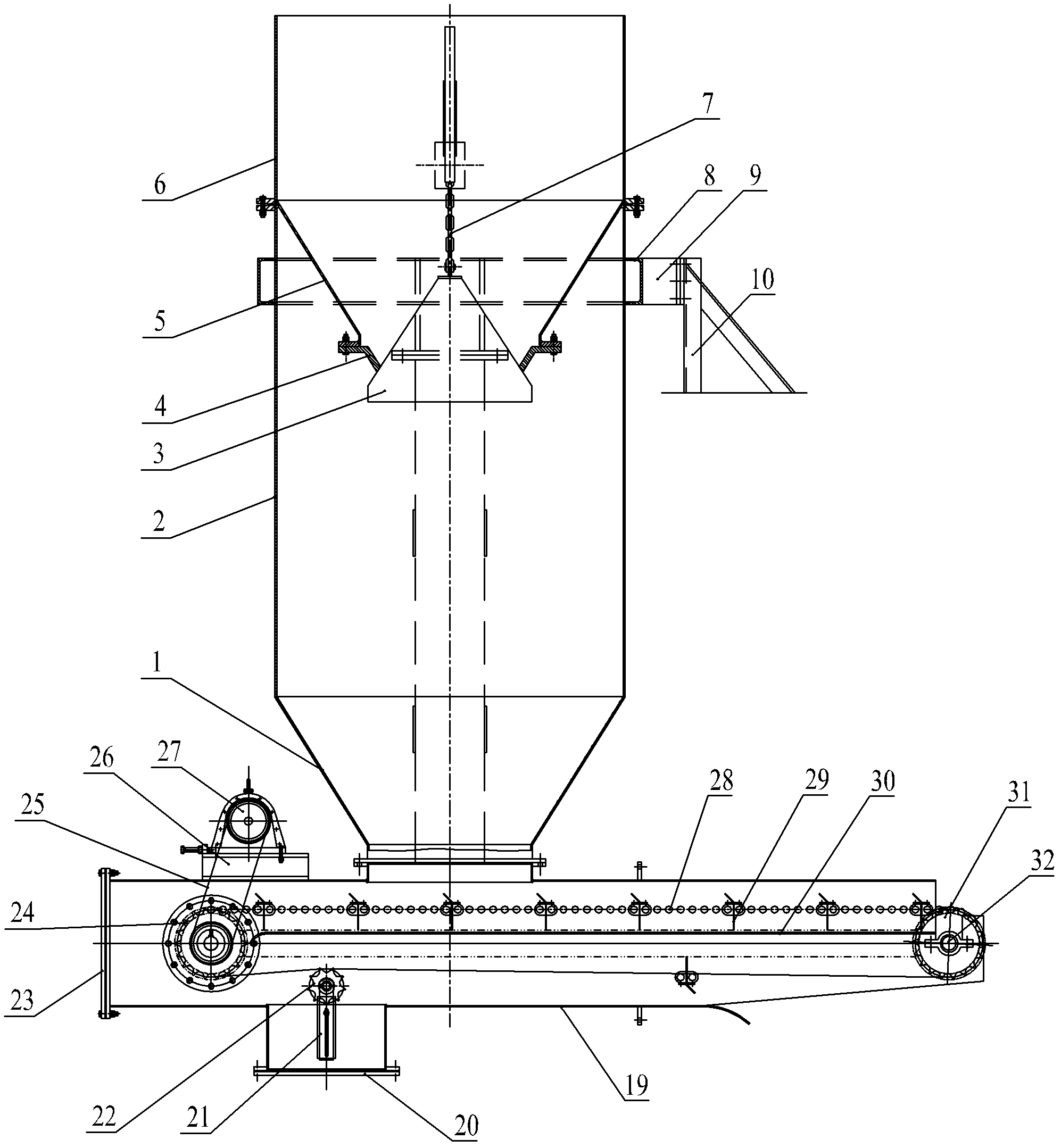
[0025] As shown in the figure: the feeding equipment of the biomass gasification furnace in the embodiment is mainly composed of two parts: a feeding device and a feeding conveyor.

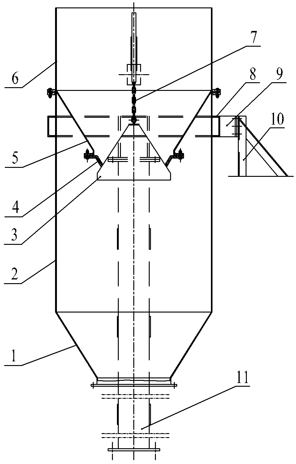
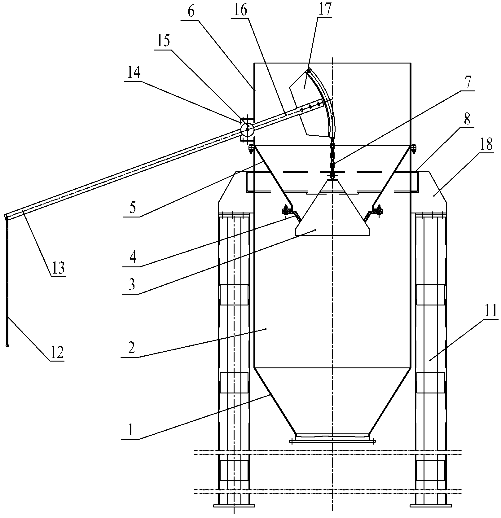
[0026] The structure of the unloading device is as Figure 1~Figure 4 As shown, it is mainly composed of a connecting seat 1, a lower cylinder body 2, a bell valve body 3, a valve seat 4, a tapered seat 5, an upper cylinder body 6, a supporting sealing frame 14, a first rod 16, a second rod 13, The chain box 17, the suspension chain 7 and the bracket mechanism are composed. The lower cylinder body 2 is supported by the bracket mechanism, and the lower end of the lower cylinder body 2 is installed with the connecting seat 1 for connecting the feeding conveyor. The lower end of the body 6 is connected, and a sealing ring is provided at the flange connection to ensure sealing; the up...


PUM


Abstract

The invention relates to feeding equipment of a biomass gasification furnace. The feeding equipment comprises a discharge device and a feeding conveyor, wherein the discharge device is arranged in the middle; a lower cylinder is supported through a bracket mechanism, the lower end of the lower cylinder is provided with a connecting seat for connecting the feeding conveyor, and the upper end of the lower cylinder is connected with the lower end of an upper cylinder through a flange; the edge of upper end of a conical seat and the inner edge of the lower end of the upper cylinder are in soldering fixation; a valve seat is arranged at the lower end of the conical seat; a bearing sealed frame is arranged on the outer wall of the upper cylinder, and is internally provided with a rotating shaft; one end of a first rod is arranged on the rotating shaft and synchronously rotate along with the rotating shaft; the other end of the first rod is provided with a chain box; a bell type wall clock cover valve body is suspended on the chain box through a suspending chain, and is matched with the valve seat to control entering of biomass; and one end of a second rod is arranged on the rotating shaft and synchronously rotates along with the rotating shaft, and a pull rod is hinged at the other end of the second rod. The feeding equipment of the biomass gasification furnace has the advantages of being smart and reasonable in structure, continuous in feeding without halt, safe in operation, stable in pressure in the furnace, uniform in feeding and clean.

Description

technical field [0001] The invention relates to a biomass gasification furnace, in particular to a feed device for a biomass gasification furnace. Background technique [0002] With the rapid development of industry and the rapid advancement of urbanization, energy shortages and environmental pollution have become the focus of attention in today's society. However, the phenomenon of burning straw and using old-fashioned wood stoves still exists in rural areas, which not only wastes raw materials, but also emits a lot of dust and greenhouse gases. At present, biomass energy waste is mainly agricultural waste, a large part of which can be used as energy. In addition, most of forestry and wood processing waste can also be used as energy. [0003] Biomass gas produced by biomass gasifier belongs to green new energy, which has strong vitality. Since the raw materials of biomass gas are crop stalks, forest wastes, edible mushroom residues, cattle, sheep and livestock dung and a...

Claims


Application Information

Patent Timeline
Patent Type & Authority Patents(China)
IPC IPC(8): C10J3/30C10J3/50
CPCY02P20/145
Inventor 徐欢
Owner 无锡湖光工业炉有限公司
Learn More