Rotary energy saving system of hydraulic excavator

A hydraulic excavator, slewing energy-saving technology, applied in the direction of earth mover/shovel, construction, etc., can solve the problems of large energy loss, complex system, high cost, etc., achieve high recovery efficiency, improve system reliability, and low cost Effect

Inactive Publication Date: 2014-06-11
SOUTH CHINA UNIV OF TECH
View PDF7 Cites 0 Cited by
  • Summary
  • Abstract
  • Description
  • Claims
  • Application Information

AI Technical Summary

Problems solved by technology

So far, there is no hydraulic system that can fully recover braking energy and avoid overflow loss during startup while satisfying slewing performance control
[0006] In order to fully save energy and recover the energy of the slewing system, the current research hotspot is the use of hybrid power, replacing the slewing hydraulic motor with a generator / motor. When braking, the inertial energy is converted into electrical energy by the generator and stored in the battery and capacitor. When starting Discharge again to drive the motor to rotate, but the electric energy recovered by braking is not enough for starting, so it is generally necessary to recover the energy of other mechanisms such as the lowering of the boom. In order to use the excess electric energy, an electric motor and the engine are required to drive the hydraulic pump in series.
The disadvantage of the gasoline-electric hybrid system is that because the energy conversion has gone through multiple links such as diesel engine, generator, battery, electric motor, hydraulic pump, hydraulic motor, etc., there is energy loss in each link, which leads to energy loss in the entire conversion process It is still relatively large, and the most important thing is that the system is complicated, the cost is high, and there are certain problems in battery life, power conversion efficiency, weight, reliability, etc., which offset the energy-saving effect that can be obtained by adopting this technology to a certain extent

Method used


Image

  • Rotary energy saving system of hydraulic excavator
  • Rotary energy saving system of hydraulic excavator
  • Rotary energy saving system of hydraulic excavator

Examples


Embodiment Construction

[0030] The specific embodiments of the present invention will be described in further detail below, but the embodiments of the present invention are not limited thereto.

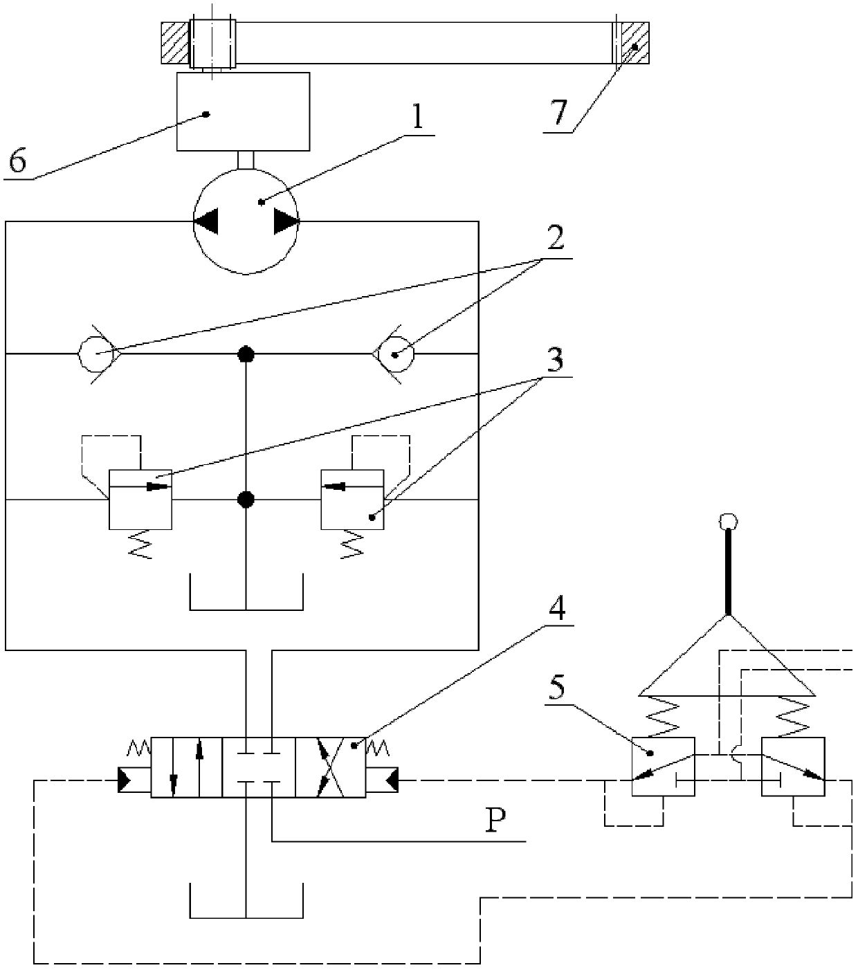
[0031] Figure 4 As shown, the hydraulic excavator rotary energy-saving system of the present invention includes the excavator rotary hydraulic system, and the rotary hydraulic system includes a main control reversing valve 4, an overload oil supply valve group, a hydraulic motor 1, and a pilot control valve 5. The overload oil supply valve group is composed of two one-way valves 2 and two overload valves 3, and the pilot control valve 5 includes two pilot valves; the inlets of the two one-way valves 2 are connected with the two overload valves 3 The outlets of the check valves 2 are connected together and then connected to the oil tank 22, and the oil outlets of the two check valves 2 are respectively connected to the main oil passage of the hydraulic motor 1. The oil inlets of the two overload valves 3 a...


PUM


Abstract

The invention discloses a rotary energy saving system of a hydraulic excavator. The rotary energy saving system comprises a two-position four-way reversing valve, an energy storage unit, a three-position four-way hydraulic control reversing valve, an air storage cylinder and two one-way valves. Outlets of the two one-way valves are connected with a lower chamber of the energy storage unit and a port P of the three-position four-way hydraulic control reversing valve while inlets of the two one-way valves are connected with an inlet oil channel and an outlet oil channel of a hydraulic motor. The energy storage unit is jointed with the two-position four-way reversing valve, a piston butts against a valve stem when being close to the end of the lower chamber so as to be capable of driving the valve stem of the reversing valve to switch, and an upper chamber is connected with an air storage cylinder. A port P and a port O of the two-position four-way reversing valve are connected with a port A and a port B of a main-control reversing valve, and the port A and the port B of the main-control reversing valve are connected with the inlet oil channel and the outlet oil channel of the hydraulic motor. Hydraulic control ports on two sides of the three-position four-way hydraulic control reversing valve are respectively in parallel connection with an oil channel from the main control reversing valve and a pilot operating valve. The roary energy saving system is easy to implement and low-cost, and has the advantages that performance of conventional rotary hydraulic systems can be kept, rotary braking energy can be restored sufficiently, efficiency is high, and overload and impact of the hydraulic motor can be improved by the energy storage unit.

Description

technical field [0001] The invention relates to the field of excavating machinery, in particular to a rotary energy-saving system for a hydraulic excavator. Background technique [0002] Such as figure 1 As shown, the hydraulic excavator is mainly composed of the getting off part 1, the slewing device 2, the upper turntable 3 and the working device. The working device mainly includes a boom cylinder 4, a boom 5, a stick cylinder 6, a stick 7, a bucket cylinder 8, a bucket 9 and a rocker linkage mechanism. The slewing device of the hydraulic excavator adopts hydraulic drive technology. The engine drives the hydraulic pump to provide hydraulic power, and the hydraulic motor drives the upper turntable 3 of the excavator to rotate through the reduction mechanism. The upper turntable 3 is connected with the working device to drive the working device to rotate. During excavation operations, the slewing device is generally in a hydraulic braking state to ensure that the working ...

Claims


Application Information

Patent Timeline
Patent Type & Authority Patents(China)
IPC IPC(8): E02F9/22
Inventor 迟永滨
Owner SOUTH CHINA UNIV OF TECH
Why Eureka
Try Eureka