Axial positioning and connecting structure of cam shaft

A technology of axial positioning and connection structure, which is applied in the direction of engine components, machines/engines, mechanical equipment, etc., can solve the problems of poor economy, poor adjustment of pressure plate manufacturing, and large amount of pressure plate scrapping, so as to improve economic benefits and improve manufacturability , The effect of reducing the scrap rate

Active Publication Date: 2012-10-03
WUXI KIPOR POWER CO LTD
View PDF5 Cites 2 Cited by
  • Summary
  • Abstract
  • Description
  • Claims
  • Application Information

AI Technical Summary

Problems solved by technology

The structural design requirements of the pressure plate are complicated, and there are certain requirements for the surface hardness of the pressure plate in actual use, thus adding a heat treatment process; due to the large deformation of the pressure plate after heat treatment, there are requirements for processing and manufacturing; the manufacturing adjustment of the pressure plate is relatively poor, The amount of scrapping of the pressure plate is relatively large, and the economy is poor; from the perspective of the installation process, it is obvious that there is an additional assembly process when the pressure plate and the camshaft are pressed together; at the same time, in order to lock the bolts on the pressure plate, due to structural limitations, the wrench can only pass through the gear. Drill holes on the top to make way for the wrench. In order to ensure the strength of the gear, the outer diameter of the gear can only be increased, which will cause the entire gear train of the engine to be bulky, resulting in an uncompact structure of the whole machine.

Method used


Image

  • Axial positioning and connecting structure of cam shaft
  • Axial positioning and connecting structure of cam shaft

Examples


Embodiment Construction

[0009] The present invention will be further described below in conjunction with specific drawings and embodiments.

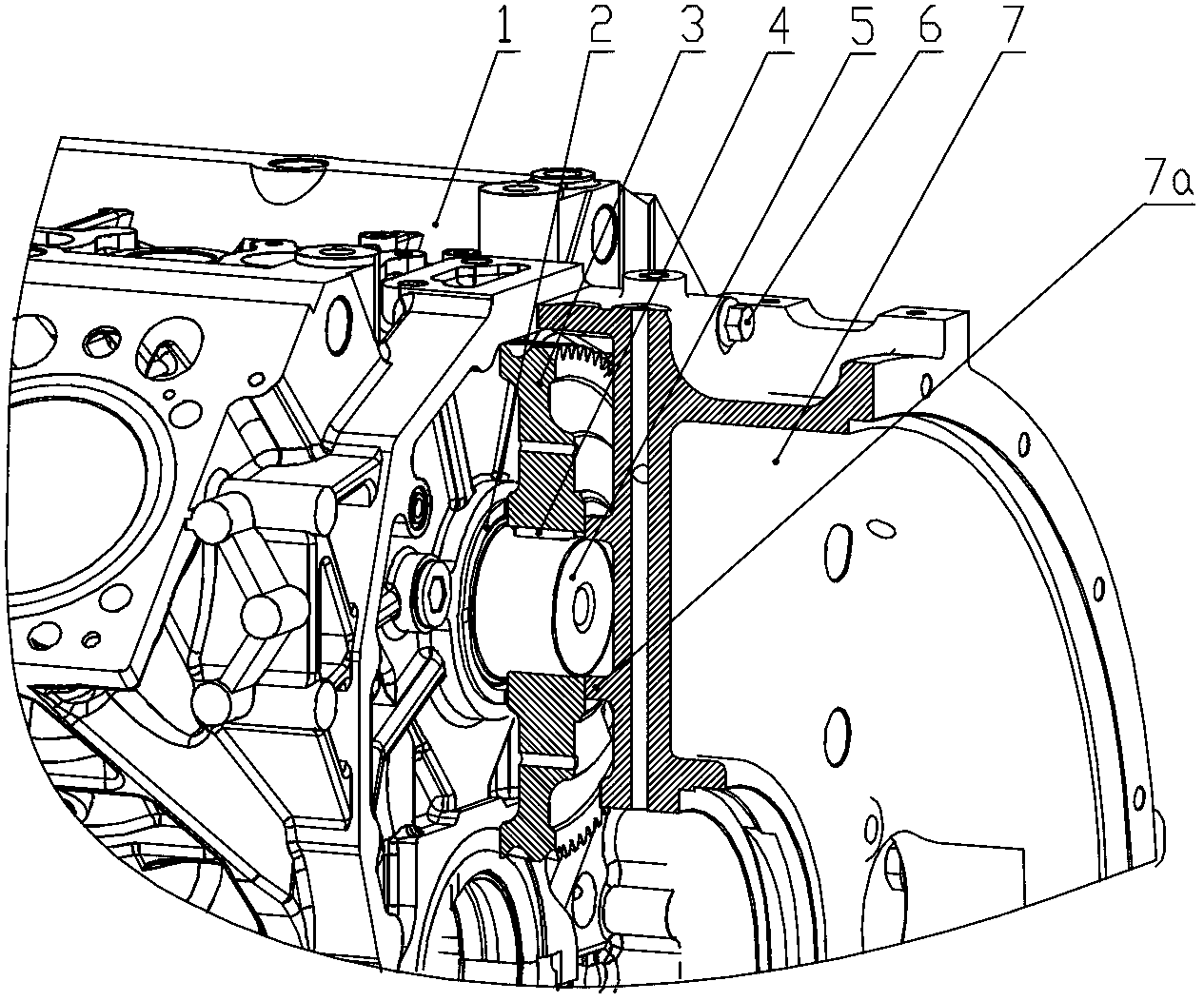
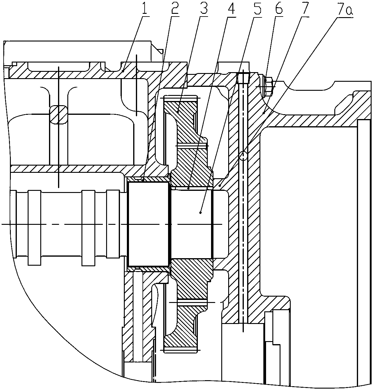
[0010] As shown in the figure: the camshaft axial positioning connection structure in the embodiment is mainly composed of an independent body 1, a camshaft thrust bush 2, a timing gear 3, a flat key 4, a camshaft 5, and a flywheel housing fastening bolt 6 Composed of components such as the flywheel housing 7, the independent body 1 in the embodiment is the body of a water-cooled engine.

[0011] Such as figure 1 , figure 2 As shown, the camshaft 5 is rotatably installed in the independent body 1, the timing gear 3 is installed on the camshaft 5 and connected to the transmission with the flat key 4, and the flywheel housing 7 is fastened to the independent body by the fastening bolt 6 of the flywheel housing. 1; the side of the flywheel housing 7 opposite to the timing gear 3 is provided with an axial positioning block 7a, and the axial positioning block 7a...


PUM


Abstract

The invention relates to an axial positioning and connecting structure of a cam shaft, comprising an independent machine body, a timing gear, a flat key, a cam shaft and a flywheel shell, wherein the cam shaft can be rotatably arranged in the independent machine body, the timing gear is arranged on the cam shaft and is connected with the flat key for realizing transmission, and the flywheel shell is fastened on the independent machine body by virtue of a flywheel shell fastening bolt. The axial positioning and connecting structure of the cam shaft is characterized in that an axial positioning block is arranged on one side of the flywheel shell, which is opposite to the timing gear, and the axial positioning block presses the end face of the timing gear to realize axial positioning of the cam shaft. According to the axial positioning and connecting structure of the cam shaft disclosed by the invention, the traditional mounting pressure plate is omitted, structural design and manufacturability are improved, rejection rate of a part is greatly reduced, and requirement for an assembly technology is also greatly reduced, and thus economic benefit is improved.

Description

technical field [0001] The invention relates to an axial positioning connection structure of a camshaft, in particular to an axial positioning connection structure device used for connecting an engine camshaft and a machine body, and belongs to the technical field of power devices. Background technique [0002] In the traditional engine camshaft connection structure, the axial positioning of the camshaft is clamped between the camshaft and the gear through the pressure plate and locked on the body through bolts, that is, the camshaft is traditionally locked on the body through the pressure plate. The structural design requirements of the pressure plate are complicated, and there are certain requirements for the surface hardness of the pressure plate in actual use, thus adding a heat treatment process; due to the large deformation of the pressure plate after heat treatment, there are requirements for processing and manufacturing; the manufacturing adjustment of the pressure pl...

Claims


Application Information

Patent Timeline
Patent Type & Authority Applications(China)
IPC IPC(8): F01L1/047
Inventor 肖亨琳韦海
Owner WUXI KIPOR POWER CO LTD
Why Eureka
Try Eureka