Independent external-mounting maintenance-free multi-stage oil and gas separator assembly

An oil-gas separator and plug-in technology, applied in the direction of machines/engines, engine components, mechanical equipment, etc., can solve problems such as poor safety, high maintenance costs, and increased crankcase pressure

Inactive Publication Date: 2014-08-13
NANCHONG LINGYUN GAOJU MFG
View PDF6 Cites 23 Cited by
  • Summary
  • Abstract
  • Description
  • Claims
  • Application Information

AI Technical Summary

Problems solved by technology

[0006] Filter-type oil-gas separator: This method is to install an oil-gas separation filter element in the separation chamber, which is made of a kind of ultra-fine synthetic fiber; due to the use of the filter element, the initial efficiency of this method is high, which can reach more than 95%; but Due to the extremely small micropores of the ultra-fine synthetic fiber filter element, the oil and carbonized particles in the oil-gas mixture are easily attached to the surface of the filter element and deposited inside the filter element, resulting in blockage of the filter element, a sharp drop in separation efficiency, an increase in resistance, and an increase in crankcase pressure. ;Especially in winter, the water vapor in the oil-air mixture adheres to the surface of the filter element and deposits inside the filter element. After the engine stops working, it will freeze and block the filter element and fail; it has been proved by actual use that the filter element will seriously fail when the engine works less than 3000KM , the security is extremely poor, the post-maintenance cost is high, and users complain a lot

Method used


Image

  • Independent external-mounting maintenance-free multi-stage oil and gas separator assembly

Examples


Embodiment 1

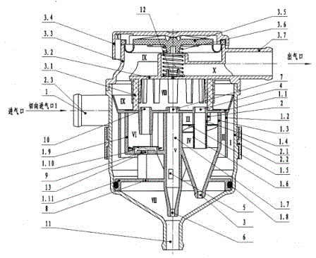
[0022] Embodiment 1, the first cyclone separation chamber is composed of the oil-gas separator shell and the oil-gas separator body shell, which is composed of the oil-gas separator body shell, the oil-gas separator cover and the outer wall of three fine separation conical tubes distributed at 90° on the circumference The second diffusion separation chamber is composed of three fine separation conical tubes distributed at 90° on the circumference and the center tube of the oil-gas separator cover. The third fine cyclone separation chamber is composed of three fine separation conical tubes distributed at 90° on the circumference and The swirling blades and the central tube of swirling blades form the fourth enhanced cyclone separation chamber, the fifth fine cyclone separation chamber is formed by the small fine separation cone tube set in the center of the circumference, and the sixth impact and diffusion chamber is composed of the safety valve cavity and safety valve. The safe...


PUM


Abstract

The invention discloses an independent external-mounting maintenance-free multi-stage oil and gas separator assembly. The oil and gas separator assembly is characterized in that a first cyclone separation cavity consists of an oil and gas separator outer shell and an oil and gas separator body shell; a second dispersing separation cavity consists of the oil and gas separator body shell, an oil and gas separator cover and the outer walls of three refine separation conical pipes which are distributed on the circumference at 90 degrees; a third refine cyclone separation cavity consists of the three refine separation conical pipes which are distributed on the circumference at 90 degrees and a central pipe; a fourth reinforcement cyclone separation cavity consists of the three refine separation conical pipes which are distributed on the circumference at 90 degrees, a central pipe, and a cyclone blade; a fifth refine cyclone separation cavity consists of a small refine separation conical pipe arranged in the center of the circumference; a sixth compact and dispersing safety separation cavity consists of a safety valve cavity and a safety valve; an eighth separation cavity consists of a respirator compact plate and a safety damping net; a flow pressure adjusting valve consists of a flow pressure adjusting diaphragm in a respirator and a flow pressure adjusting spring; any installation mechanism consists of an installation support and variable air inlet and outlet pipe included angles; and an oil return cavity consists of a separation conical pipe bottom and an independent separator shell.

Description

technical field [0001] The invention relates to a crankcase oil-gas separation system of an automobile engine, in particular to an independent external multi-stage oil-gas separator assembly for crankcase oil and gas of an automobile diesel engine. Background technique [0002] When the automobile engine is working, because there is always a certain gap between the piston ring and the cylinder liner of the engine, and the gap will continue to grow with the wear of the piston ring, there will always be a part of the combustible mixture and the exhaust gas after combustion. Intruded into the crankcase of the engine, causing the pressure in the crankcase to increase, the oil leaks from the crankshaft oil seal, crankcase gasket, oil pan gasket, etc.; the burned exhaust gas that escapes into the crankcase, due to The temperature is high, and it is continuously mixed with the engine oil during the operation of the engine, resulting in high-temperature carbonization, thinning, and ...

Claims


Application Information

Patent Timeline
Patent Type & Authority Patents(China)
IPC IPC(8): F01M13/04
Inventor 冯松柏
Owner NANCHONG LINGYUN GAOJU MFG
Why Eureka
Try Eureka