
Fault tolerance type permanent magnetic vernier motor

A vernier motor and permanent magnet technology, which is applied in the fields of electric vehicles, motors, and electrical engineering, can solve the problems that the centralized winding does not have high fault tolerance performance, cannot meet low-speed high-torque operation, and does not have the ability to operate with faults. Fault running capability, elimination of mechanical gearbox, effect of short ends

Inactive Publication Date: 2012-10-03
JIANGSU UNIV
View PDF6 Cites 20 Cited by
  • Summary
  • Abstract
  • Description
  • Claims
  • Application Information

AI Technical Summary

Problems solved by technology

[0005] Although the permanent magnet fault-tolerant motor in the prior art has high reliability and high fault-tolerant performance, because of its low torque density (similar to ordinary permanent magnet motors), when it is applied to a direct-drive electric vehicle, the motor volume Limited by the size of the tire, the output torque is also limited and cannot meet the needs of low-speed high-torque operation
[0006] The permanent magnet vernier motors in the prior art all use 3-phase armature windings and the number of slots per pole and phase q = 1 / 2 fractional slot double-layer concentrated winding structure, first q= The 1 / 2 fractional slot concentrated winding has a low winding factor (about 0.866) due to the fact that the two turns of one coil form an electrical angle of 120° in space, which reduces the back EMF and output torque to some extent
Secondly, the three-phase double-layer concentrated winding does not have high fault tolerance, and the ratio of self-mutual inductance is low, resulting in a relatively high degree of coupling between phases. When a phase fails, the magnetic field generated by the faulty phase will seriously affect the other two normal phases. Cause the system to fail to work properly and not have the ability to operate with faults

Method used


Image

  • Fault tolerance type permanent magnetic vernier motor
  • Fault tolerance type permanent magnetic vernier motor
  • Fault tolerance type permanent magnetic vernier motor

Examples


Embodiment Construction

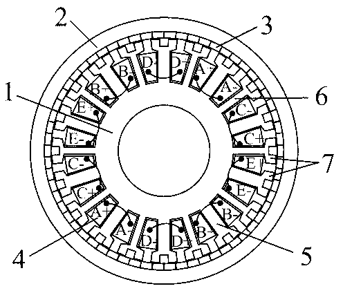
[0023] refer to figure 1 , the present invention includes an inner stator 1 , an outer rotor 2 , a permanent magnet 3 , an armature winding 4 , an armature tooth 5 , a fault-tolerant tooth 6 and a modulation pole 7 . The inner stator 1 and the outer rotor 2 are coaxial, and a permanent magnet 3 , an armature winding 4 , an armature tooth 5 , a fault tolerance tooth 6 and a modulation pole 7 are arranged between the inner stator 1 and the outer rotor 2 . Along the circumferential direction of the inner surface of the outer rotor 2, the permanent magnet 3 is fixed on the inner surface of the outer rotor 2. The material of the permanent magnet 3 is NdFeB, and the magnetization direction is radial. The N pole and S pole of the permanent magnet 3 Alternately.

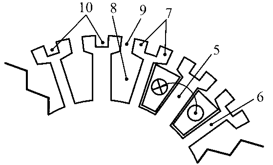
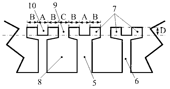
[0024] 10 armature teeth 5 and 10 fault-tolerant teeth 6 are arranged on the circumference of the inner stator 1. The armature teeth 5 and the fault-tolerant teeth 6 are interlaced with each other. A single-layer concentra...


PUM


Abstract

The invention discloses a low-speed big-torque fault tolerance type permanent magnetic vernier motor for an electric automobile. The fault tolerance type permanent magnetic vernier motor comprises an inner stator and an outer rotor which are coaxial, wherein a permanent magnet is fixedly adhered to the inner surface of the outer rotor along the circumferential direction; the magnetizing direction of the permanent magnet is radial; the N pole and the S pole are arranged staggeredly; 10 armature teeth and 10 fault tolerance teeth are distributed on the circumference of the inner stator staggeredly; a single layer of concentrated armature winding is wound on the armature teeth; concentrated armature windings on the two armature teeth and radially opposite to each other are connected in series into one phase; the armature winding is a five-phase winding; the tooth width of the armature teeth is not equal to that of the fault tolerance teeth; and 40 modulation poles are distributed on the tooth tops of the armature teeth and the fault tolerance teeth uniformly along the circumferential direction. The torque density is greatly increased; the fault tolerance performance is remained; the volume of the motor is reduced; and the reliability and the operation ability with fault of the motor are improved.

Description

technical field [0001] The invention relates to the fields of electricians, motors and electric vehicles, in particular to a five-phase permanent magnet fault-tolerant vernier motor for low-speed and high-torque electric vehicles. Background technique [0002] With the increasing oil price and environmental pollution crisis, electric vehicles have begun to receive more and more attention. Unlike traditional vehicles, the propulsion system of electric vehicles is mainly driven by high-performance electric motors. Therefore, the electric motor is a key component that determines the efficiency and performance of electric vehicles. [0003] Compared with the existing electric excitation motor or brushed DC motor drive system, the permanent magnet brushless motor has the advantages of high efficiency, simple and compact structure, reliable operation, small size and light weight. With the emergence of hub motors with an outer rotor structure, the mechanical connection between the...

Claims


Application Information

Patent Timeline
IPC IPC(8): H02K21/12H02K1/27H02K1/16
CPCY02T10/641Y02T10/64
Inventor 刘国海杨俊勤赵文祥陈前瞿沥
Owner JIANGSU UNIV
Learn More