
Submerging jet flow testing box and testing method

A test box and jet technology, which is applied in the testing of mechanical components, fluid dynamics testing, and testing of machine/structural components, etc., can solve the actual differences in test results, and it is difficult to record the acceleration mechanism of abrasive particles in submerged abrasive jets. stay and other issues

Active Publication Date: 2012-10-10
CHONGQING UNIV
View PDF5 Cites 22 Cited by
  • Summary
  • Abstract
  • Description
  • Claims
  • Application Information

AI Technical Summary

Problems solved by technology

The application of water jet in actual engineering is completed under submerged conditions. However, most of the current research on water jet structures is still under non-submerged conditions, and there is a big difference between the test results and the actual engineering.
Difficult to document acceleration mechanisms of abrasive particles in submerged abrasive jets in combination with other test instruments
A small number of studies on jet structure under submerged conditions also have the problem of not being able to use non-contact methods
In addition, there is currently no suitable test device for jet structure test experiments under submerged conditions

Method used


Image

  • Submerging jet flow testing box and testing method
  • Submerging jet flow testing box and testing method
  • Submerging jet flow testing box and testing method

Examples


Embodiment Construction

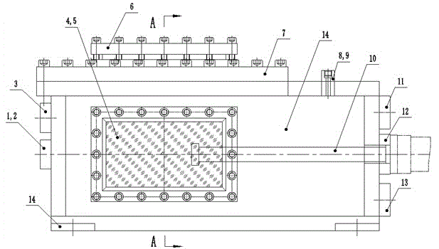
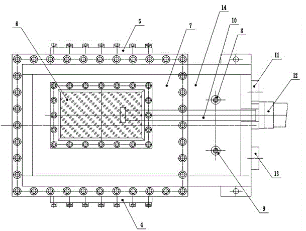
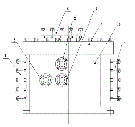
[0016] see figure 1 , figure 2 , image 3 and Figure 4 , the test box includes a box body 14, glass windows 4, 5, 6, jet water inlets 1, 2, 3, holder 10, feeding device 12, pressure gauge interface 8, air release port 9, liquid flow valve port 11 And discharge port 13 etc.

[0017] The glass window 6 is on the top cover of the casing, surrounded by steel plate pressing, connected with the top cover 7 by bolts, and the top cover 7 is connected with the casing 14 by bolts. Glass window 4,5 is on the front and back wall of casing, and edge is pressed with steel plate all around, also connects respectively on the casing 14 by bolt. During the test, the laser of the 3DPIV system (three-dimensional laser particle imaging velocimeter) can be injected into the jet fluid in the test box through the glass window 6, and the high-speed camera can take pictures of the jet fluid structure through the glass window 5, and the experimenter can directly pass through the glass window 4. O...


PUM


Abstract

The invention discloses a submerging jet flow testing box and a testing method. The testing box includes a box body, jet flow water inlets, a vision window, a pressure gauge interface, a relief port, a clamp holder, a feeding device interface, a liquid stream valve port, a drainage port and the like. During the laboratory experiment process, a submerging fluid field environment is improved, and the approximate engineering practical submerging jet flow is simulated; other testing instrument is combined, the submerging jet flow fluid field structure is observed; the potential core of jet under the submerging condition is observed combined with a three dimensional laser particle imaging velocimeter (3DPIV) system; the variation of different jet nozzle jet flow fluid field structures is analyzed, and the internal structures of the jet nozzles are optimized; the accelerating mechanism and distribution condition of grinding material particles during the submerging grinding material jet flow testing are analyzed; and meanwhile, the observation experiment for cutting and flushing material under the submerging condition can be performed. The submerging jet flow testing box and the testing method have the advantages that the structure is simple, the operation is convenient, nozzles can be replaced easily, a plurality of testing functions are provided, and compared with other jet flow testing devices, the submerging jet flow testing box not only can test the jet flow fluid field structure under the submerging condition, but also can be reutilized repeatedly, thereby saving the experimental expense at the same time.

Description

technical field [0001] The invention relates to a water jet test device, in particular to a submerged jet test box, which is suitable for testing the jet structure in the submerged state through an optical observation instrument, testing the jet flow constant velocity core of the nozzle outlet under the submerged condition through 3DPIV, and testing the jet flow of nozzles with different parameters Structure, testing the acceleration mechanism and distribution of abrasive particles in the submerged abrasive jet and the erosion of materials under submerged conditions. Background technique [0002] As a highly efficient cutting, crushing and cleaning technology, high-pressure water jet technology has been widely used in more than a dozen industries such as mining, chemical industry, aerospace, transportation, etc., especially in the petroleum industry, which has brought huge economic and social benefits. benefit. The application of water jet in actual engineering is completed...

Claims


Application Information

Patent Timeline
Patent Type & Authority Applications(China)
IPC IPC(8): G01M10/00G01M13/00G01N15/00
Inventor 葛兆龙卢义玉夏彬伟程亮汤积仁贾亚杰梅绪东周哲杨枫
Owner CHONGQING UNIV
Learn More