Voltage regulator module

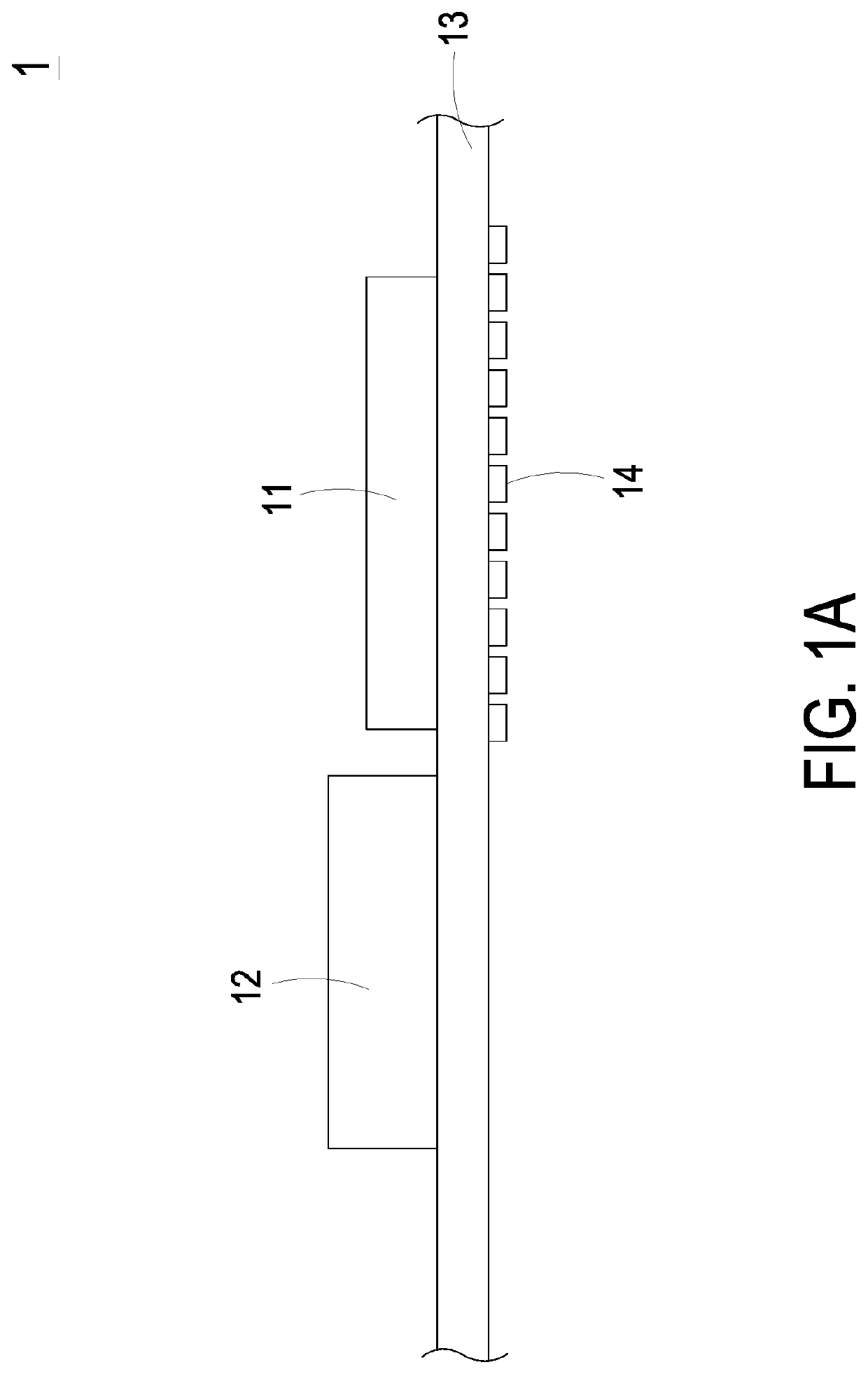
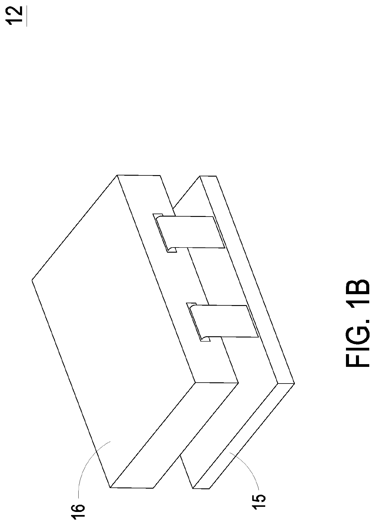
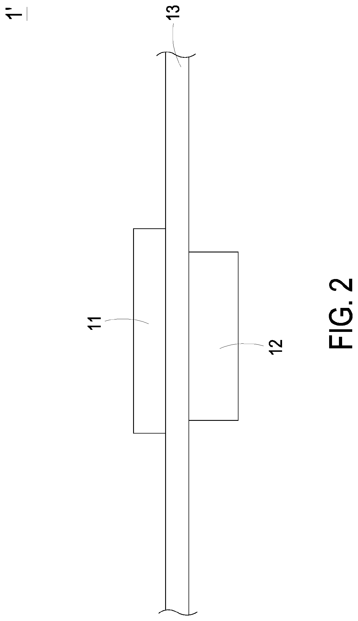
a voltage regulator and module technology, applied in the direction of process and machine control, electronic device control, electronic device association, etc., can solve the problems of voltage regulator module b>12/b> not being able to effectively transfer voltage regulator module b>12/b> not being able to withstand the pressure of heat sink and spring screws, etc., to achieve effective transfer of heat to the casing, effectively withstanding pressure, and discharging heat through the cas

Active Publication Date: 2020-04-09
DELTA ELECTRONICS INC
View PDF0 Cites 0 Cited by
  • Summary
  • Abstract
  • Description
  • Claims
  • Application Information

AI Technical Summary

Benefits of technology

[0009]An object of the present disclosure provides a voltage regulator module capable of effectively transferring the heat to a casing of an electronic device, dissipating the heat through the casing and effectively withstanding the pressure from a heat sink and spring screws.

Problems solved by technology

Firstly, the heat from the voltage regulator module 12 cannot be effectively transferred to the casing of electronic device 1′ and dissipated away through the casing of the electronic device 1′.
Secondly, the voltage regulator module 12 is unable to withstand the pressure from the heat sink and the spring screws.
In case that the force applied to the ball grid arrays is not uniform, the soldering material is possibly cracked or detached and the product reliability is impaired.
However, the installation space of the output capacitor is restricted.
That is, the voltage regulator module 12 cannot be equipped with more output capacitors according to the practical requirements.
Since the gap between every two pins of the signal communication part is large, the number of pins mounted on the given area is limited.
Moreover, since the cross-section area of each pin is small, the reliability of mounting the pin is usually unsatisfied.
In case that the soldering materials between the pins are connected, a short-circuited problem occurs.

Method used


Image

  • Voltage regulator module
  • Voltage regulator module
  • Voltage regulator module

Examples


Embodiment Construction

[0031]The present disclosure will now be described more specifically with reference to the following embodiments. It is to be noted that the following descriptions of preferred embodiments of this disclosure are presented herein for purpose of illustration and description only. It is not intended to be exhaustive or to be limited to the precise form disclosed.

[0032]Please refer to FIGS. 3A, 3B and 4. FIG. 3A is a schematic exploded view illustrating a voltage regulator module according to a first embodiment of the present disclosure and taken along a viewpoint. FIG. 3B is a schematic exploded view illustrating the voltage regulator module of FIG. 3A and taken along another viewpoint. FIG. 4 is a schematic equivalent circuit diagram illustrating the voltage regulator module of FIG. 3A. The voltage regulator module 3 may be installed in an electronic device. In case that the central processing unit of the electronic device requires a large amount of current, the voltage regulator modu...


PUM


Abstract

A voltage regulator module includes a first circuit board assembly and a signal communication part. The first circuit board assembly includes a plurality of first conduction pads. The signal communication part is arranged on the first circuit board assembly. The signal communication part includes a conduction circuit board with a plurality of conduction fingers and a plurality of surface pins. The plurality of conduction fingers are formed on at least one lateral side of the conduction circuit board. The plurality of surface pins are electroplated on a top side and a bottom side of the conduction circuit board. A first end of each conduction finger is contacted with the corresponding surface pin on the top side. A second end of each conduction finger is contacted with the corresponding surface pin on the bottom side. The signal communication part is fixed on and electrically connected with the first circuit board assembly.

Description

CROSS-REFERENCE TO RELATED APPLICATION[0001]This application claims the benefit of U.S. Provisional Application Ser. No. 62 / 743,251 filed on Oct. 9, 2018, claims the benefit of U.S. Provisional Application Ser. No. 62 / 770,432 filed on Nov. 21, 2018, claims priority to China Patent Application No. 201811519655.4 filed on Dec. 12, 2018, and claims priority to China Patent Application No. 201910900101.7 filed on Sep. 23, 2019, the entire contents of which are incorporated herein by reference for all purposes.FIELD OF THE INVENTION[0002]The present disclosure relates to a voltage regulator module, and more particularly to a voltage regulator module capable of reducing loss, increasing heat dissipation efficiency, withstanding increased pressure, disposing more output capacitors therein and / or decreasing the volume thereof.BACKGROUND OF THE INVENTION[0003]Please refer to FIGS. 1A and 1B. FIG. 1A schematically illustrates the structure of a conventional electronic device. FIG. 1B schemati...

Claims


Application Information

Patent Timeline
Patent Type & Authority Applications(United States)
IPC IPC(8): H05K1/14H05K1/11H05K1/09H05K1/18H05K1/02H02M3/158
CPCH05K1/185H05K2201/10318H05K2201/1003H05K1/181H05K2201/10734H05K1/144H05K1/09H05K2201/09509H05K1/111H05K2201/10015H05K2201/10416H05K2201/10166H05K1/0204H02M3/1584H02M2003/1586H05K2201/10053H05K2201/041H01R12/57H01R12/58H01F17/06H01F2017/067H02M1/327H02M3/1586H02M3/003
Inventor XIONG, YAHONGJIN, DASU, QINGHUA
Owner DELTA ELECTRONICS INC
Why Eureka
Try Eureka