
Monopulse antenna angle simulation tracking method

An antenna angle and monopulse technology, applied in the field of aircraft measurement and control, can solve the problem of lack of low cost in the measurement and control system, and achieve the effect of normal self-tracking and good tracking performance of the servo system

Active Publication Date: 2012-10-10
10TH RES INST OF CETC
View PDF4 Cites 31 Cited by
  • Summary
  • Abstract
  • Description
  • Claims
  • Application Information

AI Technical Summary

Problems solved by technology

[0006] The measurement and control system lacks a low-cost environment that can check and simulate the tracking performance of the equipment at any time. The receiver together forms an angle tracking closed-loop system to achieve the purpose of preparing the personnel for the task, assisting training in the capture process, and checking the dynamic performance of the equipment

Method used


Image

  • Monopulse antenna angle simulation tracking method
  • Monopulse antenna angle simulation tracking method
  • Monopulse antenna angle simulation tracking method

Examples


Embodiment Construction

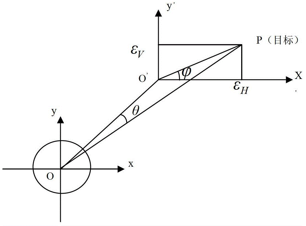
[0025] refer to figure 1 . Most of the dual-channel monopulse tracking system antennas in the measurement and control station adopt multi-mode feed structure, and the mathematical modeling of the angle error signal of the dual-channel monopulse system is carried out. When receiving a single-frequency signal, the XOY plane measurement coordinate system is established with the center of the three axes of the antenna as the origin. When the angle error θ is small, the sum signal (Σ) received by the antenna can be expressed by formula (1):

[0026] the s Σ (t)=Acosω c t (1)

[0027] The differential signal (Δ) can be expressed by formula (2):

[0028]

[0029] where: ω c is the single-frequency signal frequency, A is the signal amplitude, μ is the antenna normalized difference slope, θ is the angle between the incident radio wave and the electric axis of the antenna, is the angle between the projection of the incident radio wave on the XOY plane and the X axis.

[0030]...


PUM


Abstract

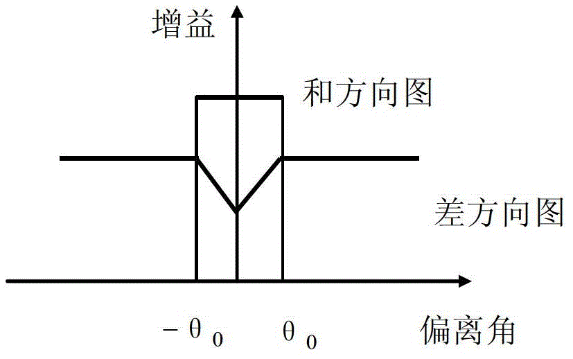
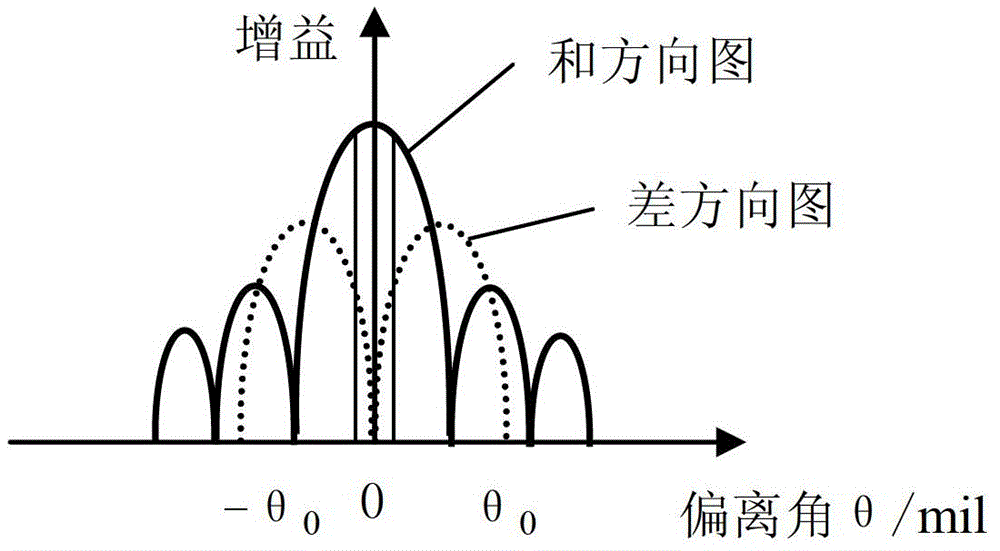
The invention provides a monopulse antenna angle simulation tracking method, which aims at providing an environment for inspecting and simulating equipment tracking performance at any time to a shooting range monitor system. The method is characterized by comprising the following steps of: establishing an XOY plane measurement coordinate system by taking the center of three axes of an antenna as an original point; constructing a simulation circuit according to an antenna pattern simplified model; drawing four calibration curves of a sum and different signal magnitude difference-deviation angle relationship, sum and difference signal amplitude different-error voltage relationship, deviation angle-error voltage relationship and deviation angle-AGC (automatic gain control) voltage relationship on each angle beyond the main beam of the antenna, and establishing a data mapping table; acquiring the controlled variable of an angle deviation control circuit and simulating to generate a radio frequency tracking signal according to a method of checking a signal amplitude mapping table; and demodulating and extracting an angle error signal by receiving link amplification and down-conversion in an intermediate frequency tracking receiver; and feeding position and pitch angle error voltage to an antenna control unit to complete angle closed-ring tracking.

Description

technical field [0001] The invention relates to the field of aircraft measurement and control, and relates to a simulation method for angle tracking of an antenna system in a monopulse tracking system. Background technique [0002] In the prior art, for the training simulator used by the shooting range measurement and control system, the simulation content includes many specific contents such as angular tracking performance simulation, ranging dynamic simulation, radial velocity simulation, telemetry and remote control function simulation, digital transmission reception demodulation performance simulation, etc. . Among them, the simulation of angle tracking performance requires real-time and accurate real-time response capability because of the simulated angle closed-loop feedback system; in addition, in order to ensure the accuracy of the simulation, it is necessary to design a high-precision, small-step attenuator, so the simulation is more difficult. [0003] Angle captu...

Claims


Application Information

Patent Timeline
IPC IPC(8): G05D3/12
Inventor 苏勋席文君刘咏
Owner 10TH RES INST OF CETC
Learn More