Dual-input full-isolation integrated current transformer

A fully isolated, dual-input technology, applied in the direction of converting DC power input to DC power output, instruments, adjusting electrical variables, etc., can solve the problems of uneven power density and large voltage amplitude variation range.

Inactive Publication Date: 2012-10-10
YANSHAN UNIV
View PDF5 Cites 13 Cited by
  • Summary
  • Abstract
  • Description
  • Claims
  • Application Information

AI Technical Summary

Problems solved by technology

However, new energy generally has shortcomings such as uneven power density and large voltage amplitude variation range. If a voltage-type multi-port converter is used as the topology of power conversion, it is necessary to introduce a more complex control method to compensate for the voltage amplitude variation. Impact

Method used


Image

  • Dual-input full-isolation integrated current transformer
  • Dual-input full-isolation integrated current transformer
  • Dual-input full-isolation integrated current transformer

Examples


Embodiment 1

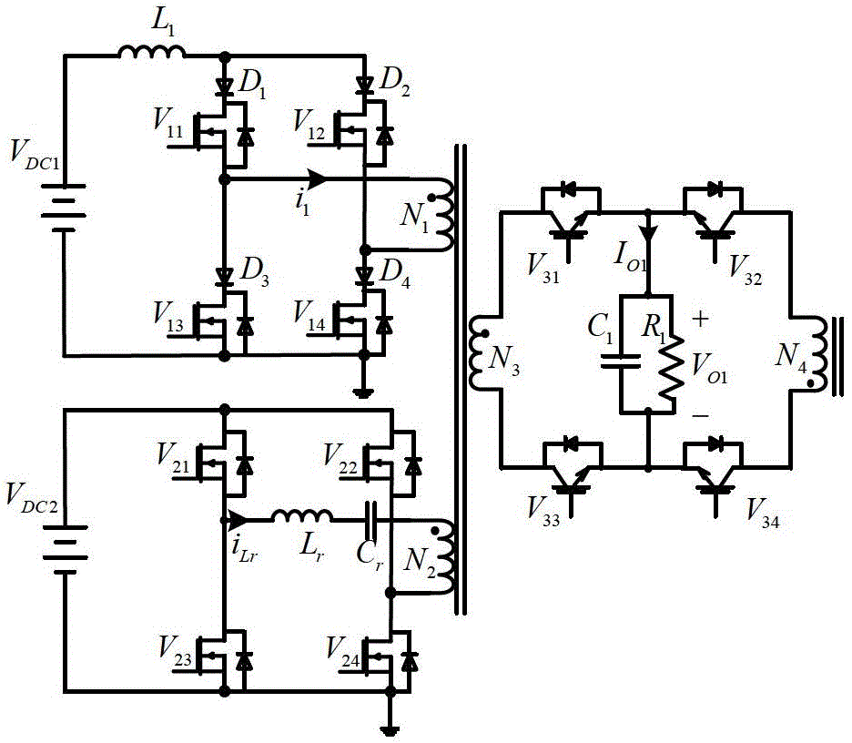
[0030] A dual-input fully isolated integrated converter:

[0031] Such as figure 1 As shown, the first front-stage current-mode full-bridge conversion circuit uses a power switch tube V with an internal anti-parallel diode 11 , V 12 , V 13 , V 14 and respective series connected power diodes D 1 、D 2 、D 3 、D 4 Composed of a full-bridge circuit structure with reverse voltage blocking capability and unidirectional current flow, where the power diode D 1 The cathode of the power switch tube V 11 drain of the power diode D 2 The cathode of the power switch tube V 12 drain of the power diode D 3 The cathode of the power switch tube V 13 drain of the power diode D 4 The cathode of the power switch tube V 14 the drain of the DC input supply V DC1 The positive pole of the input inductor L 1 One end of the input inductance L 1 The other end of the power diode D 1 and D 2 anode of the DC input power supply V DC1 The negative pole of the power switch tube V 13 and V ...

Embodiment 2

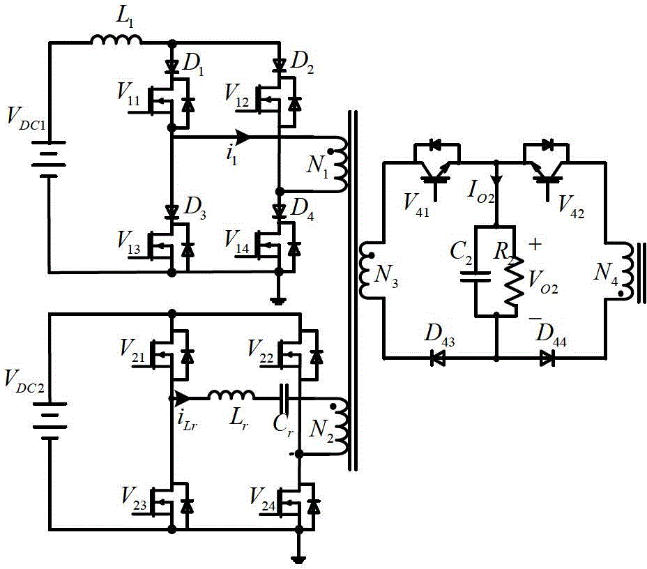
[0037] A dual-input fully isolated integrated converter:

[0038] Such as figure 2 As shown, the first front-stage current-mode full-bridge conversion circuit uses a power switch tube V with an internal anti-parallel diode 11 , V 12 , V 13 , V 14 and respective series connected power diodes D 1 、D 2 、D 3 、D 4 Composed of a full-bridge circuit structure with reverse voltage blocking capability and unidirectional current flow, where the power diode D 1 The cathode of the power switch tube V 11 drain of the power diode D 2 The cathode of the power switch tube V 12 drain of the power diode D 3 The cathode of the power switch tube V 13 drain of the power diode D 4 The cathode of the power switch tube V 14 the drain of the DC input supply V DC1 The positive pole of the input inductor L 1 One end of the input inductance L 1 The other end of the power diode D 1 and D 2 anode of the DC input power supply V DC1 The negative pole of the power switch tube V 13 and V ...

Embodiment 3

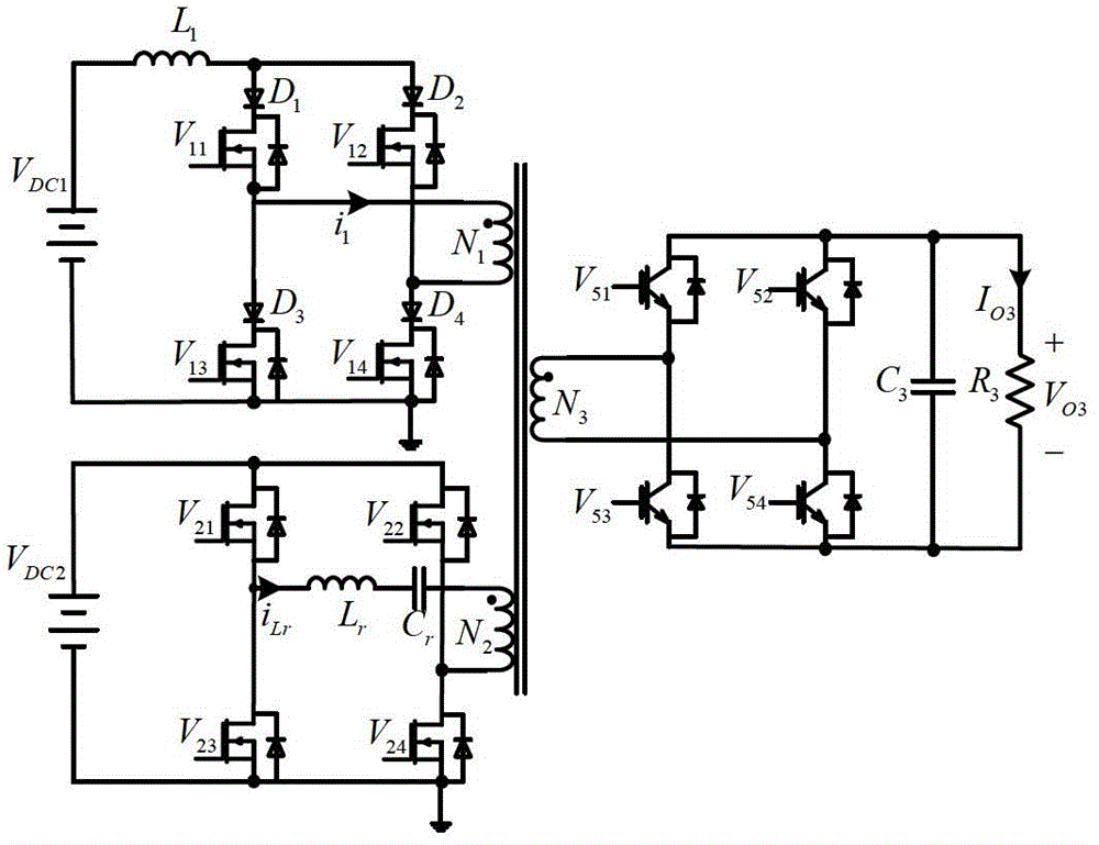
[0044] A dual-input fully isolated integrated converter:

[0045] Such as image 3 As shown, the first front-stage current-mode full-bridge conversion circuit uses a power switch tube V with an internal anti-parallel diode 11 , V 12 , V 13 , V 14 and respective series connected power diodes D 1 、D 2 、D 3 、D 4 Composed of a full-bridge circuit structure with reverse voltage blocking capability and unidirectional current flow, where the power diode D 1 The cathode of the power switch tube V 11 drain of the power diode D 2 The cathode of the power switch tube V 12 drain of the power diode D 3 The cathode of the power switch tube V 13 drain of the power diode D 4 The cathode of the power switch tube V 14 the drain of the DC input supply V DC1 The positive pole of the input inductor L 1 One end of the input inductance L 1 The other end of the power diode D 1 and D 2 anode of the DC input power supply V DC1 The negative pole of the power switch tube V 13 and V ...


PUM


Abstract

The invention discloses a dual-input full-isolation integrated current transformer. The dual-input full-isolation integrated current transformer comprises a current type full-bridge transformation circuit of a first front-stage input port, a series resonance full-bridge transformation circuit of a second front-stage input port, a high-frequency isolation transformer and a back-stage rectifier circuit. A current type full-bridge transformer is used to realize inversion of a high-frequency square wave of an input direct-current current source and achieve soft switching of a switch tube in the adopted phase shift PWM (Pulse Width Modulation) control way at the same time; a series resonance transformer is used to realize transformation of a high-frequency sine current of an input direct-current voltage source; a multi-winding transformer is used to realize coupling isolation transmission of the high-frequency square wave current and the sine current on the input sides; the two input ports cannot be influenced by transformer voltage clamping; and all the primary winding voltages of the transformers are reduced value of output voltage. Moreover, the introduced series resonance process that a resonance inductor and a resonance capacitor have the same frequency as a switch realizes transformation from an input power source to a resonance current source and achieves switch changeover of all power tubes at a zero crossing point of resonance current so as to reduce circuit loss.

Description

technical field [0001] The invention relates to an integrated dual-input converter capable of realizing DC-AC-DC energy conversion, in particular to a dual-input three-port DC / DC converter integrated with a current source type full-bridge converter and a series resonant converter . The converter uses a current-mode full-bridge converter to realize the high-frequency square wave inversion of the input DC current source, uses a series resonant converter to realize the high-frequency sinusoidal current conversion of the input voltage source, and uses a multi-winding transformer to realize the high-frequency square wave inverter on the input side. A dual-input three-port DC / DC converter for coupled isolation transmission of wave current and sinusoidal current. Background technique [0002] With the continuous popularization of new energy products, a large number of topological structures suitable for clean energy power supply have emerged. Among them, multi-port converters are ...

Claims


Application Information

Patent Timeline
Patent Type & Authority Applications(China)
IPC IPC(8): H02M3/335
CPCY02B70/1433Y02B70/10
Inventor 孙孝峰李昕张宇环裴光明姚帅
Owner YANSHAN UNIV
Why Eureka
Try Eureka