Cutter shaft control method of leading line yielding track in blade helical milling process

A technology of blade helix and control method, used in milling machine equipment, manufacturing tools, details of milling machine equipment, etc.

Active Publication Date: 2012-10-17
NORTHWESTERN POLYTECHNICAL UNIV
View PDF7 Cites 12 Cited by
  • Summary
  • Abstract
  • Description
  • Claims
  • Application Information

AI Technical Summary

Problems solved by technology

[0004] In order to solve the problems existing in the prior art, the present invention proposes a tool axis control method for the edge head avoidance track in the process of blade helical milling, which involves the design of the blade containing cylinder, the design of the edge head avoidance curve, and the generation of the avoidance track tool axis.

Method used


Image

  • Cutter shaft control method of leading line yielding track in blade helical milling process
  • Cutter shaft control method of leading line yielding track in blade helical milling process
  • Cutter shaft control method of leading line yielding track in blade helical milling process

Examples


Embodiment Construction

[0048] Describe the present invention below in conjunction with specific embodiment:

[0049] In this embodiment, the five-axis annular cutter machining of a blade of a certain type of aeroengine is taken as an example, and the trajectory of the cutter position point in the curved surface area of ​​the blade body is calculated according to the second-order Taylor approximation algorithm, wherein the radius R of the annular cutter is 8 mm.

[0050] In this embodiment, the tool axis control method of the edge avoidance track includes the following steps:

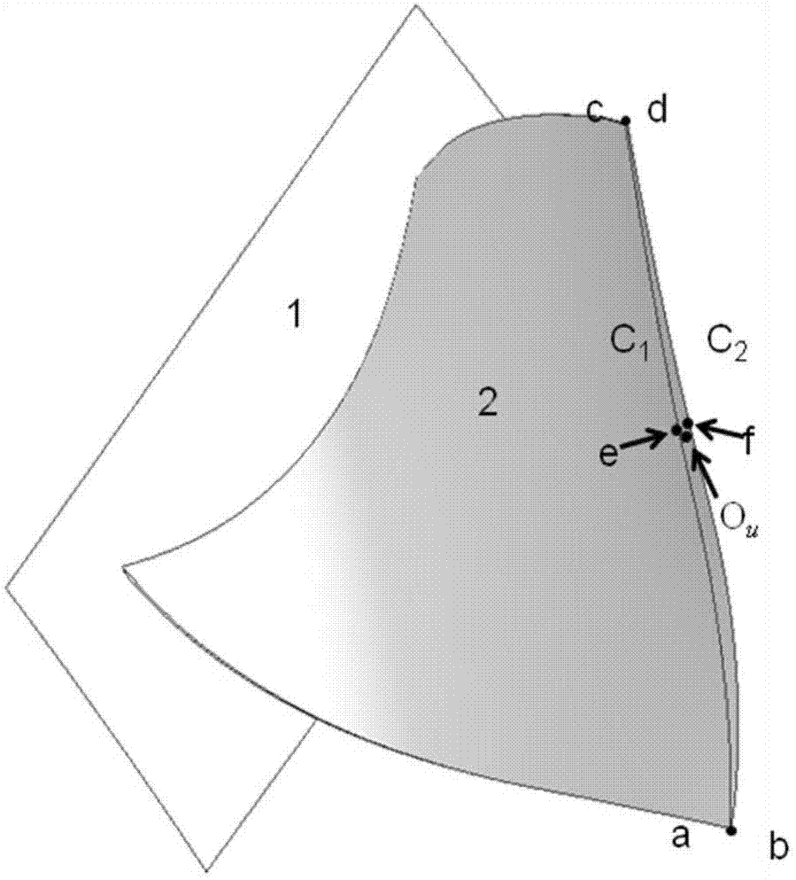
[0051] Step 1: Construct the cylindrical auxiliary surface of the blade:

[0052] The auxiliary surface of the blade containing cylinder is a tool to realize the avoidance curve of the edge head. The key to determine the cylindrical surface is the center of the top circle, the center of the bottom circle and the radius of the cylinder. figure 1 shown. The curved surface of the blade body (the curved surface of the blade basi...


PUM


Abstract

The invention provides a cutter shaft control method of a leading line yielding track in a blade helical milling process, comprising the following steps of: firstly, configuring a blade cylinder auxiliary face; secondly, taking a containing cylindrical face as an auxiliary face and constructing a leading line yielding curve; and finally, taking an outer normal vector of the cylindrical face as auxiliary information of vector interpolation of a cutter shaft of a leading line yielding track line, so as to obtain the cutter shaft vector of the leading line yielding track. The method disclosed by the invention has commonality and is suitable for spiral machining of a blade body of any blade; and the leading line yielding curve and the cutter shaft vector of a cutter site on the yielding curve can be effectively generated. Actual production verifies that the cutter shaft vector generated by the method is stable and smooth, the machining quality and the machining efficiency of the blade are improved and the service life of a machine tool and a tool is prolonged.

Description

technical field [0001] The invention relates to the technical field of blade machining, in particular to a method for controlling a cutter axis of an edge avoidance track during blade helical milling. Background technique [0002] Engine blades, especially aeroengine blades, have complex shapes and harsh working environments, requiring them to have precise dimensions, precise shapes, and strict surface integrity. They are usually formed by multi-axis CNC milling processes. The milling methods used in the CNC machining process of the blade are point milling, side milling and helical milling. Due to the advantages of less clamping times, continuous cutting trajectory and high processing efficiency, helical milling has attracted widespread attention in the industry. However, the edge head is the most important area affecting the machining quality of the blade helical milling, so the treatment of the front and rear edge surfaces of the blade adopts the method of reserving a cer...

Claims


Application Information

Patent Timeline
Patent Type & Authority Applications(China)
IPC IPC(8): B23C3/00
Inventor 杨建华张娟吴宝海张定华胡述龙韩飞燕张莹罗明
Owner NORTHWESTERN POLYTECHNICAL UNIV
Why Eureka
Try Eureka