Marine flying lifesaving method and device

A technology of equipment and flying cranes, which is applied to sea and air rescue equipment, life rafts, aircraft, etc., and can solve problems such as the inability to implement lifesaving operations in sea disasters

Active Publication Date: 2012-10-17
郑鹏
View PDF7 Cites 54 Cited by
  • Summary
  • Abstract
  • Description
  • Claims
  • Application Information

AI Technical Summary

Problems solved by technology

Long-distance shipwreck rescue operations that exceed the round-trip distance of a helicopter cannot be implemented

Method used


Image

  • Marine flying lifesaving method and device
  • Marine flying lifesaving method and device
  • Marine flying lifesaving method and device

Examples


specific Embodiment

[0954] Figure 19 Mark the schematic diagram of the lifesaving method and equipment of the movable flying crane on the deck of the sea-going ship.

[0955] The marine flying crane lifesaving system is composed of flying crane 1 水Under the pulling effect of the energy transmission traction cable L, the power transmission energy is supplied, and the control of the operator of the deck movable type control room (264) or the deck bridge fixed type control room (276) flies to the sea surface and hovers over the person who fell into the water. Hanger 1 水 The lowering and lowering net catcher 261 is lowered to the surface of the water for rescue, and the life-saving operation of flying cranes at sea is carried out.

[0956] Two. Flying device 1 water specific embodiment:

[0957] (1). The preferred scheme for the specific implementation of the pneumatic mechanism of the flying crane:

[0958] 1. Optimal scheme for the large-diameter main duct rotor body 5 of the flying crane:

...

Embodiment approach

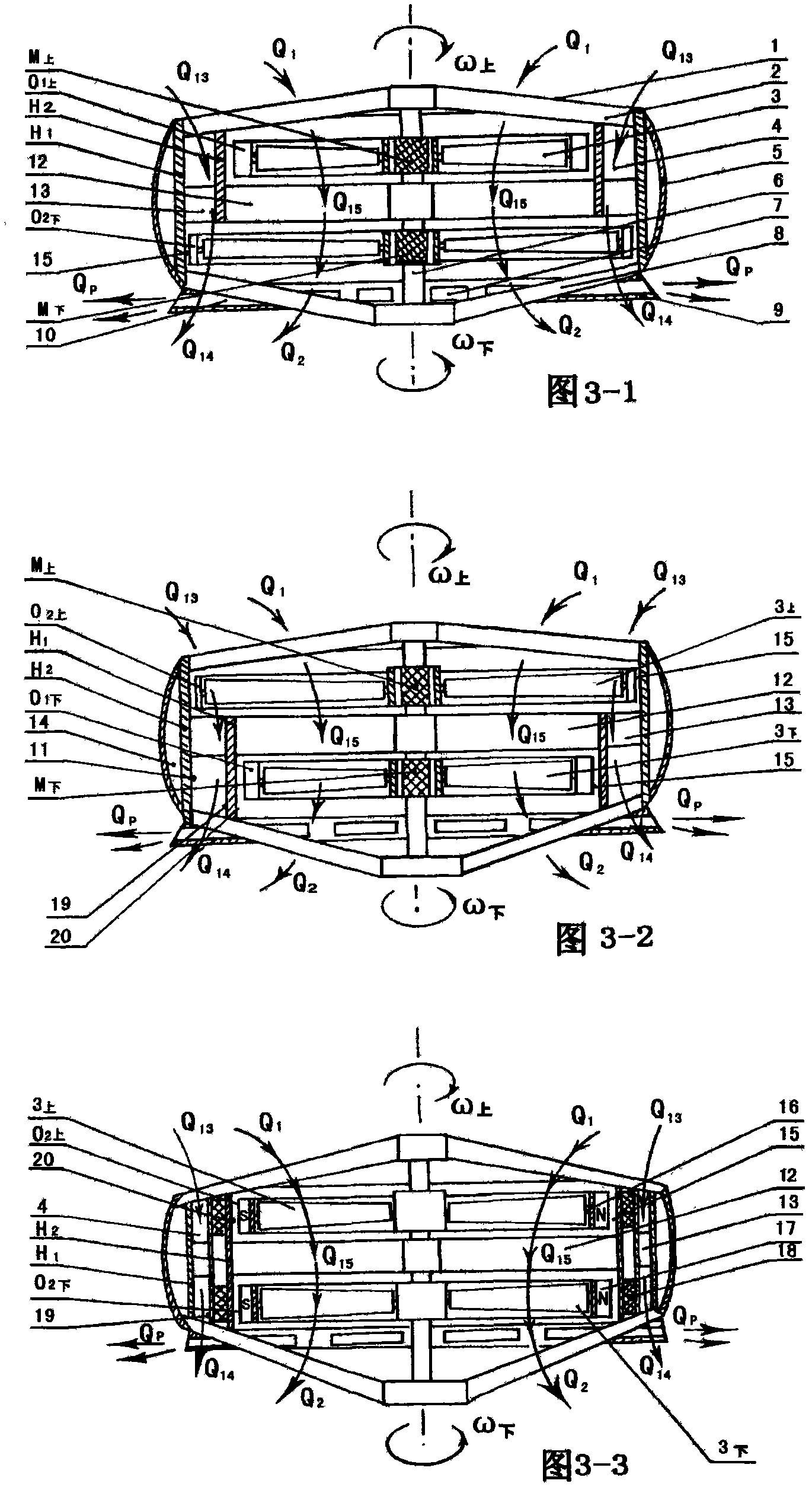
[0990] Figure 6-1 It is the rotor motor structure and the liquid jet variable inertia system 30 喷 Main section view.

[0991] Figure 6-2 It is liquid jet variable inertia system 30 喷 Axonometric cutaway view.

[0992] The characteristic function of the variable inertia mechanism: set the variable inertia mechanism in the coaxial upper and lower rotor system, fan system and propeller system. Its function enables the upper and lower main rotors of the flying crane to produce the upper and lower differential variable inertia to induce the fixed axis of the gyro effect, and achieve the function of the ability to resist turbulent and sudden shear wind.

[0993] (1).Preferred liquid spray type variable inertia mechanism 30 喷 Structural composition and working principle:

[0994] ①. Liquid spray type variable inertia mechanism 30 喷 Overall structure composition:

[0995] In the single-ring or double-ring main duct, with the central axis 6 as the center, the space between th...


PUM


Abstract

The invention discloses a scheme of a flying lifesaving system fixedly or movably arranged on the bridge or deck, characterized in that: a large-diameter main ducted coaxial reversible dual-rotor body is used for bearing main lift; small-diameter ducted rotor bodies are symmetrically arranged around the large-diameter main ducted coaxial reversible dual-rotor body in the same plane, connecting arms can freely move in the forms of stretching, twisting, shaking and swinging, thus the effects of bearing assistant lift, mainly controlling the direction and resisting vortex ring are achieved; and a variable inertia system and an energy delivery dragging cable system are arranged in the main rotor. The device can resist turbulent flow sudden shearing transition winds and has anti-adverse wind long-endurance submersible capability, can fly within the length of the dragging cable or the distance of wireless remote like helicopter rescue principles under sea conditions in bad weather and directly fly beyond the persons in water to hover to conduct marine salvage; and can land on the water surface to float to release rescue devices to let the persons in water enter, and swan the rescue devices by using the motive force of the rotors and the pulling force of the energy delivery dragging cable to the lifeboats to save people, thus the rescue scheme and equipment of the rescue devices under sea conditions in bad weather are achieved.

Description

[0001] [Related fields]: The present invention relates to life-saving equipment and methods for large ships in rivers and seas to be rescued in water. [technical background]: [0002] In the prior art, the ship is equipped with a life buoy, and the lifeboat that is equipped on the large ocean-going giant ship. However, in the case of strong winds and waves, extreme weather and sea conditions or at night, the large ship will have a very large drop with the waves and the sea conditions, and it should not be too close to the person who fell into the water. Or the distance that can be obtained by the person who fell into the water is not easy to rescue. In case of falling into the water, the body is weak and the floating victims cannot be salvaged. If lifeguards are sent to the sea to drive a lifeboat to perform manual rescue operations, it is very difficult and dangerous, posing a threat to the lifeguards’ personal safety, and lifeguards cannot go to the sea to rescue them. . R...

Claims


Application Information

Patent Timeline
Patent Type & Authority Applications(China)
IPC IPC(8): B64C27/02B64C27/04B63C9/01B66D1/00
Inventor 郑鹏
Owner 郑鹏
Why Eureka
Try Eureka