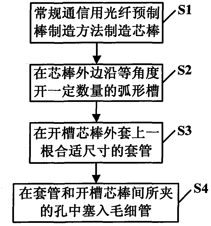
Manufacturing method of porous optical fiber preform
A technology of a holey optical fiber and a manufacturing method, which can be applied to manufacturing tools, glass manufacturing equipment, etc., can solve the problems of poor optical fiber polarization model characteristics, affecting the normal service life of optical fibers, and asymmetric circumferential force, so as to improve polarization model characteristics and bending. Loss characteristics, ensuring high cleanliness control issues, and ensuring the effect of cleanliness control
- Summary
- Abstract
- Description
- Claims
- Application Information
AI Technical Summary
Problems solved by technology
Method used
Image

Examples
Embodiment 1
[0033] Example 1: VAD process, opening six arc-shaped grooves with an arc angle of 320 degrees
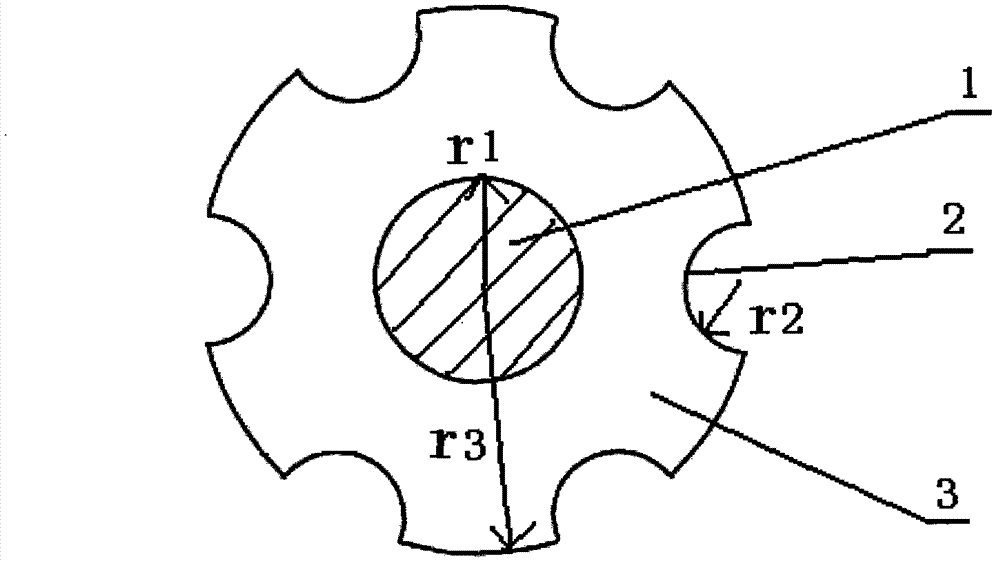
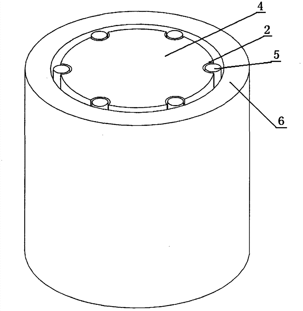
[0034] The germanium-doped mandrel 4 is prepared by VAD technology, the radius r3 of the quartz cladding 3 of the mandrel 4 is 15 mm, the radius r1 of the germanium-doped core 1 is 5 mm, and the out-of-roundness of the core 1 is within 0.8%. The relative refractive index difference between the germanium-doped core layer 1 and pure quartz glass is 0.35%. see figure 2 As shown, on the outer edge of the germanium-doped mandrel 4, open six arc-shaped slots 2 with an arc angle of 320 degrees, the radius r2 of the arc-shaped slots 2 is 3mm, and the centers of the six arc-shaped slots 2 form equilateral six For the six corners of the angle, the distance between the center of the circle and the center of the core layer 1 is 12mm. Soak the mandrel 4 with the arc-shaped groove 2 in acid solution to remove impurities, clean it with deionized water, and then dry it in a clean oven.
[0035...
Embodiment 2
[0037] Embodiment 2: PCVD process, open 12 semicircular slots
[0038] The germanium-doped mandrel 4 is prepared by PCVD technology, the radius r3 of the quartz cladding 3 of the mandrel 4 is 12 mm, the radius r1 of the germanium-doped core layer 1 is 2.5 mm, and the out-of-roundness of the core layer 1 is within 1.2%. The relative refractive index difference between the germanium-doped core layer 1 and pure quartz glass is 0.25%. Then at the periphery of germanium-doped core rod 4, open 12 semicircular grooves, the radius of groove is 0.8mm, the circle center of 12 semicircle grooves forms 12 angles of equilateral 12 deformation, and circle center is positioned at core rod 4 The distance between the outer edge and the center of the mandrel 4 is 12mm. Soak the mandrel 4 with the semicircular groove in acid solution to remove impurities, clean it with deionized water, and then dry it in a clean oven.
[0039] A quartz casing 6 of a corresponding size is placed on the core rod...
Embodiment 3
[0041] Embodiment 3: MCVD process, opening three semicircular slots
[0042] The germanium-doped mandrel 4 is prepared by MCVD technology, the radius r3 of the quartz cladding 3 of the mandrel 4 is 10mm, wherein the radius r1 of the germanium-doped core layer 1 is 2.0mm, and the out-of-roundness of the core layer 1 is 1.0%. The relative refractive index difference between the germanium core layer 1 and pure quartz glass is 0.05%. Then in the periphery of germanium-doped core rod 4, open three semicircular grooves, the radius of groove is 1mm, and the circle center of three semicircle grooves forms three angles of equilateral triangle, and circle center is positioned at the outer edge of core rod 4 , the distance from the center of mandrel 4 is 10mm. Soak the mandrel 4 with the semicircular groove in acid solution to remove impurities, clean it with deionized water, and then dry it in a clean oven.
[0043] A quartz casing 6 of a corresponding size is placed on the mandrel 4 ...
PUM
| Property | Measurement | Unit |
|---|---|---|
| Outer diameter | aaaaa | aaaaa |
| Outer diameter | aaaaa | aaaaa |
| Diameter | aaaaa | aaaaa |
Abstract
Description
Claims
Application Information
 - R&D
- Intellectual Property
- Life Sciences
- Materials
- Tech Scout
- Unparalleled Data Quality
- Higher Quality Content
- 60% Fewer Hallucinations
Browse by: Latest US Patents, China's latest patents, Technical Efficacy Thesaurus, Application Domain, Technology Topic, Popular Technical Reports.
© 2025 PatSnap. All rights reserved.Legal|Privacy policy|Modern Slavery Act Transparency Statement|Sitemap|About US| Contact US: help@patsnap.com