
Detection device

A detection device, light detection technology, applied in the direction of measuring device, scattering characteristic measurement, material analysis using sound wave/ultrasonic wave/infrasonic wave, etc., can solve the problem that the fingerprint spectrum cannot be measured, and the quantitative analysis of extremely trace substances is not specified and impossible Problems such as qualitative detection of sample molecules to achieve the effect of improving reliability

Inactive Publication Date: 2012-10-17
SEIKO EPSON CORP
View PDF10 Cites 8 Cited by
  • Summary
  • Abstract
  • Description
  • Claims
  • Application Information

AI Technical Summary

Problems solved by technology

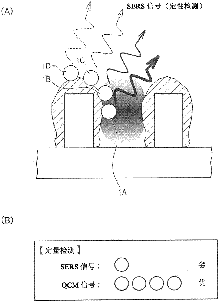
In Patent Document 4, it is pointed out that the quantitative analysis precision of both SPR and QCM is about 1 ng / cm 2 (Paragraph 0003, 0005), and pointed out that the two quantitative analysis signals are complementary (paragraph 0102), but there is no specific explanation on how to perform quantitative analysis based on the two signals, especially how to perform quantitative analysis on extremely trace substances
Moreover, since neither the attenuated total reflection surface plasmon resonance (SPR) nor QCM can measure the fingerprint spectrum of the sample molecules that should be quantified, it is technically impossible to qualitatively detect the sample molecules.

Method used


Image

  • Detection device
  • Detection device
  • Detection device

Examples


Embodiment Construction

[0035] Next, preferred embodiments of the present invention will be described in detail. In addition, the present embodiment described below does not unduly limit the content of the present invention described in the claims, and all the configurations described in the present embodiment are not necessarily necessary solutions for the present invention.

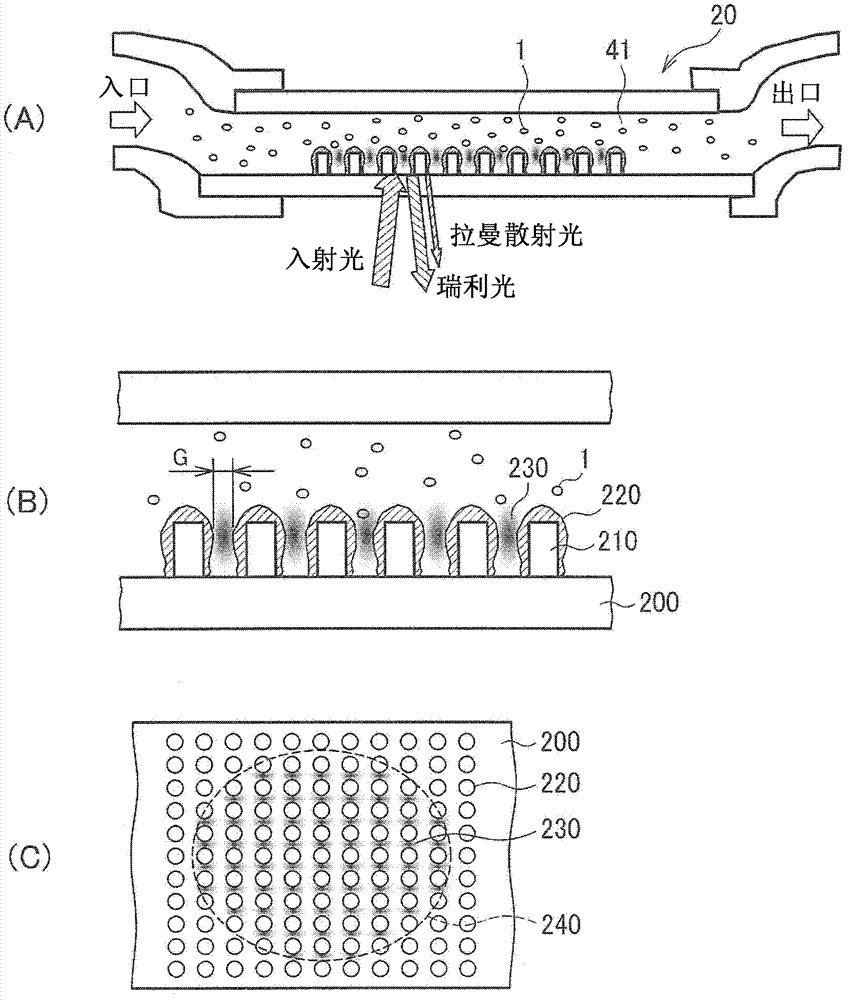
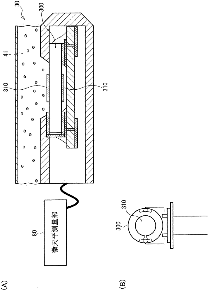
[0036] Such as Figure 5 or Figure 6 As shown, a detection device 10A according to an embodiment of the present invention is provided with two sensor chips, one is a SERS sensor chip 20 as an optical device, and the other is a microbalance sensor chip 30 . First, the two sensor chips 20 and 30 will be described.

[0037] 1. SERS sensor chip (optical device)

[0038] use figure 1 (A) to figure 1In (C), the sensor chip 20 is described. The sensor chip 20 is an optical device that emits light reflecting the adsorbed fluid sample by irradiating light, and detects Raman scattered light. An explanatory diagram showing the pri...


PUM


Abstract

A detection device includes a flow channel for a fluid sample, a suction section adapted to draw the fluid sample into the flow channel, an optical device disposed in the flow channel, a light source adapted to irradiate the optical device with light, a light detection section adapted to detect light emitted from the optical device, a microbalance sensor chip having a piezoelectric substrate provided with an oscillation electrode, and disposed in the flow channel, and a quantitative analysis section adapted to perform quantitative analysis on the fluid sample based on output from the light detection section and the microbalance sensor chip. The optical device has a metal nanostructure including projections ranging in size from 1 through 1000 nm, and emits light representing the fluid sample adsorbed to the metal nanostructure.

Description

technical field [0001] The present invention relates to a detection device and the like for quantitatively analyzing an extremely trace substance to be qualitatively analyzed. Background technique [0002] In recent years, SERS (Surface Plasmon Resonance) using SPR (Surface Plasmon Resonance), especially SERS (Surface Plasmon Resonance) using LSPR (Localized Surface Enhanced Raman Scattering (Surface Enhanced Raman Scattering) spectroscopy (Patent Documents 1 and 2) has attracted attention. The so-called SERS is that Raman scattered light is enhanced to 10 on the metal surface with nano-scale concave-convex structure. 2 ~10 14 double phenomenon. Single-wavelength excitation light such as laser light is irradiated onto sample molecules. The spectrum detects the scattered wavelength (Raman scattered light) that deviates from the wavelength of the excitation light only by the molecular vibrational energy of the sample molecule, thereby obtaining the fingerprint spectrum of ...

Claims


Application Information

Patent Timeline
Patent Type & Authority Applications(China)
IPC IPC(8): G01N5/02
CPCG01N21/658G01N21/554G01N21/55G01N2291/02809G01N5/02G01N2291/0215G01N29/022G01N21/474G01N21/553
Inventor 山田耕平桥元伸晃
Owner SEIKO EPSON CORP
Learn More