Bracket for measuring head of flying-probe tester and design method of bracket

A technology of flying probe testing machine and design method, which is applied in the field of flying probe testing machines, can solve problems such as inability to guarantee quality and long development cycle of the probe bracket, and achieve the effects of moderate rigidity, short development cycle, and guaranteed test accuracy

Active Publication Date: 2012-10-17
HANS CNC SCI & TECH
View PDF8 Cites 5 Cited by
  • Summary
  • Abstract
  • Description
  • Claims
  • Application Information

AI Technical Summary

Problems solved by technology

The development cycle of the traditional flying probe tester probe holder is long and the quality cannot be guaranteed

Method used


Image

  • Bracket for measuring head of flying-probe tester and design method of bracket
  • Bracket for measuring head of flying-probe tester and design method of bracket
  • Bracket for measuring head of flying-probe tester and design method of bracket

Examples


Embodiment Construction

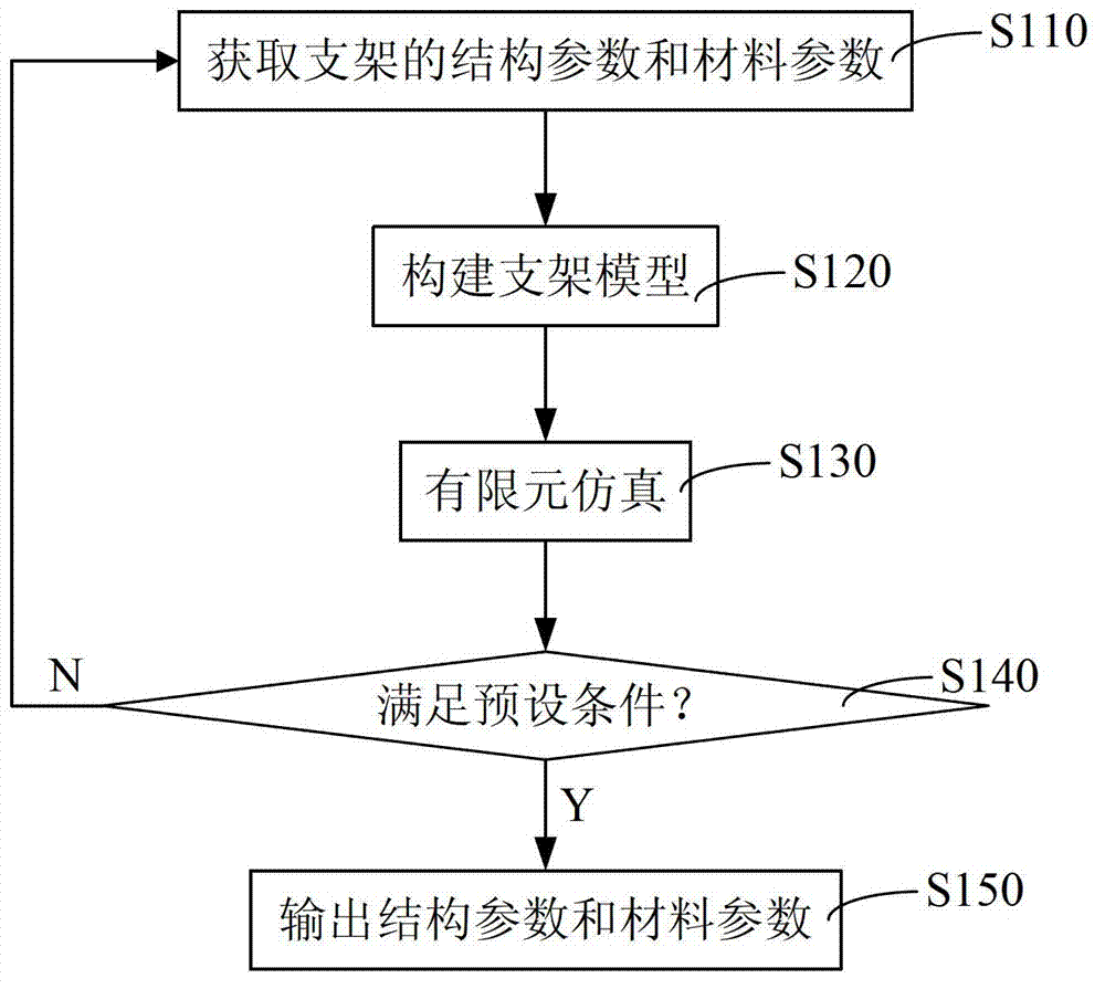
[0019] Please refer to figure 1 , this embodiment discloses a method for designing a probe bracket of a flying probe testing machine, which includes the following steps:

[0020] Step S110, acquiring structural parameters and material parameters of the stent.

[0021] Step S120, constructing a scaffold model according to the structural parameters and material parameters of the scaffold.

[0022] Step S130, performing finite element simulation on the bracket model.

[0023] Step S140, judging whether the simulation result satisfies the preset condition, if yes, execute step S150, if not, return to step S110.

[0024] Step S150, outputting the structural parameters and material parameters of the bracket.

[0025] This method of constructing the bracket model and adopting finite element simulation has a short development period and can guarantee the quality. The bracket designed according to this method meets the material and structural requirements, and can keep the test nee...


PUM


Abstract

The invention relates to a design method of a bracket for a measuring head of a flying-probe tester. The design method comprises the following steps of: acquiring structural parameters and material parameters of the bracket; constructing a bracket model according to the structural parameters and the material parameters of the bracket; performing finite element simulation on the bracket model; and when a simulation result is in accordance with preset conditions, outputting the structural parameters and the material parameters of the bracket. The bracket which is designed according to the method meets material and structural requirements; and after a test probe is subjected to reverse thrust of a contact surface of a printed circuit board (PCB), the test probe and the contact surface can keep still relative to each other in the backward movement process, and a test probe head cannot be heavily deflected, so testing accuracy is ensured, and scratches can be avoided. Meanwhile, the bracket is moderate in rigidness, and the problems of recessing of the PCB caused by over-high rigidness, high deformation caused by over-low rigidness and over-short service life can be solved. Moreover, the invention also provides the bracket which is designed according to the method.

Description

technical field [0001] The invention relates to a flying probe testing machine, in particular to a measuring head support and a design method of a flying probe testing machine. Background technique [0002] Flying probe tester is a system for testing PCB (Printed Circuit Board, printed circuit board) in a manufacturing environment. Flying probe test is one of the methods to check the electrical function of PCB (open and short circuit test). The flying probe testing machine moves each test pin to a fixed unit to be tested, and the test pins contact the pads and via holes of the test PCB to test a single component of the unit to be tested. The size of the pads and through-holes of the PCB is very small. If the test accuracy is to be ensured, the test needle will be pushed back by the contact surface after touching the PCB pad and through-hole to be tested, and the test needle should not be too large during the backward movement. offset. At the same time, the test pins are sm...

Claims


Application Information

Patent Timeline
Patent Type & Authority Applications(China)
IPC IPC(8): G01R1/04G01R31/28
Inventor 谭艳萍宋福民王星李宁高云峰
Owner HANS CNC SCI & TECH
Why Eureka
Try Eureka