Rotary compressor inspiration structure
A rotary compressor and compressor technology, applied in the field of compressors, can solve the problems of affecting the performance of the compressor, reducing the volumetric efficiency of the compressor, and insufficient suction of the lower cylinder
- Summary
- Abstract
- Description
- Claims
- Application Information
AI Technical Summary
Problems solved by technology
Method used
Image
Examples
Embodiment 1
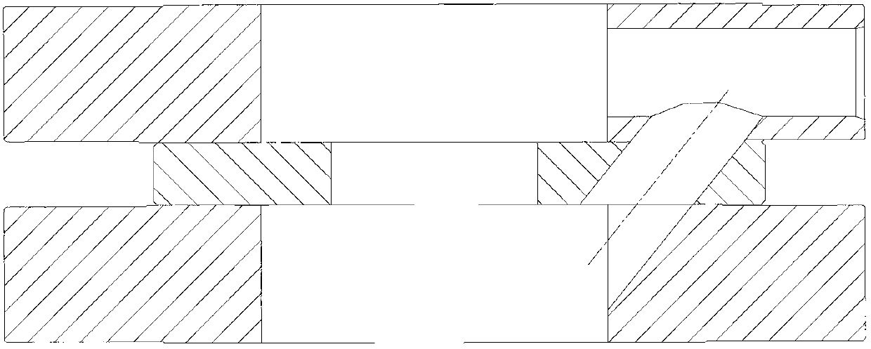
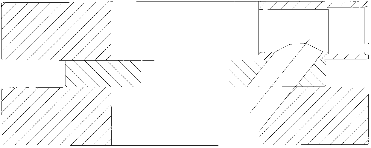
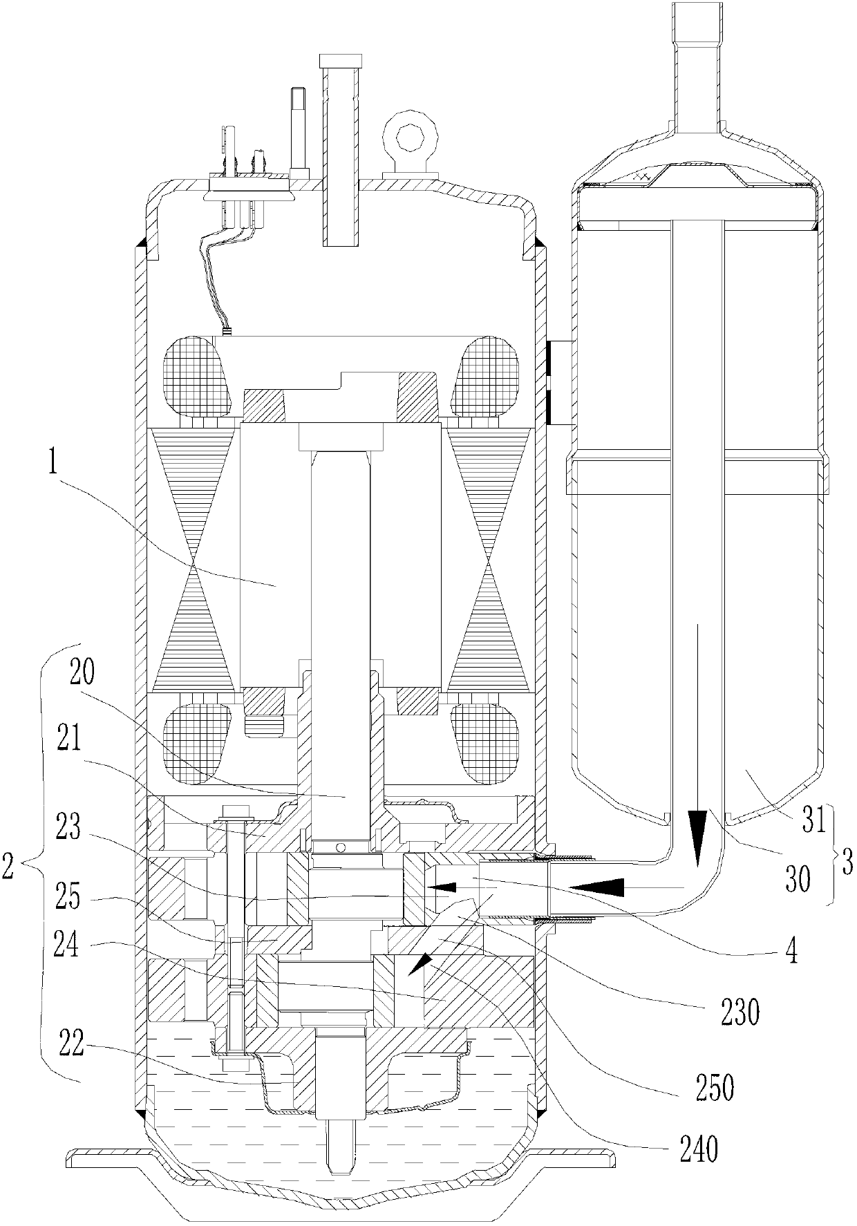
[0048] A rotary compressor suction structure, such as Figure 14 As shown, it includes a motor 1, a compressor body 2 and a suction pipe assembly 3 connected to the compressor body. The minimum diameter of the air intake hole corresponding to the suction pipe assembly in the compressor body 2 is d, and the nominal value of the rotary compressor is The working volume is set as V(cm 3 ), the cooling capacity per unit mass of the rotary compressor is set to q(J / kg), the motor speed is n(r / min), and the specific volume of the refrigerant under the national standard test conditions is v; then the theoretical exhaust gas per second Quantity V 总 For: V 总 =n·V / 60(cm 3 / s); the corresponding mass flow rate is: Then the cooling capacity Q per second is theoretically: The minimum diameter of the air intake hole in the compressor body is d (mm) (d is actually the smallest inner diameter of the entire suction channel from the inner tube of the liquid separator to the double-cylinder...
Embodiment 2
[0059] Such as Figure 3 to Figure 11 , Figure 13 to Figure 14 As shown, on the basis of Embodiment 1, in addition to satisfying the minimum diameter of the air inlet In addition, in this embodiment, the compressor body 2 is a two-cylinder rotary compressor, the suction pipe assembly 3 includes a suction pipe 30 and a liquid separator 31 connected thereto; the compressor body 2 includes a crankshaft 20, an upper flange 21 , the lower flange 22, the first cylinder 23, the second cylinder 24 and the partition 25 arranged between the first and second cylinders, the crankshaft 20 is installed on the motor 1, the lower flange 22 is arranged at the end of the crankshaft 20, and the upper The flange 21 is installed on the crankshaft 20 at the lower end of the motor 1; when the first cylinder 23 is the upper cylinder, the corresponding second cylinder 24 is the lower cylinder; when the first cylinder 23 is the lower cylinder, the corresponding second cylinder 24 is the upper cylind...
Embodiment 3
[0061] Such as Figure 3 to Figure 11 , Figure 13 to Figure 14 As shown, in addition to meeting the basic requirements in Embodiment 2, in this embodiment, the second cylinder 24 (lower cylinder) directly communicates with the minimum diameter d2 of the suction groove of the compression chamber and the first cylinder 23 (upper cylinder) directly communicates with the first cylinder 23 (upper cylinder) to compress The ratio of the minimum diameter d1 of the suction hole of the cavity has a significant impact on the increase rate of the cooling and heating capacity of the compressor. As shown in Table 3, the single-suction double-cylinder inverter compressor selected by the testing machine has a displacement of 42.8, the second cylinder 24 is the lower cylinder, and the minimum suction diameter d2 of the second cylinder 24 directly connected to the compression chamber is 14mm. Change; the first cylinder 23 is the upper cylinder, change the size of the minimum diameter d1 of th...
PUM
 Abstract
Description
Claims
Application Information
 - R&D
- Intellectual Property
- Life Sciences
- Materials
- Tech Scout
- Unparalleled Data Quality
- Higher Quality Content
- 60% Fewer Hallucinations
Browse by: Latest US Patents, China's latest patents, Technical Efficacy Thesaurus, Application Domain, Technology Topic, Popular Technical Reports.
© 2025 PatSnap. All rights reserved.Legal|Privacy policy|Modern Slavery Act Transparency Statement|Sitemap|About US| Contact US: help@patsnap.com


