Equipment and method for automatic glue baking of optical transceiver assembly

A technology for optical transceivers and assemblies, which is applied in the field of baking glue for optical transceiver assemblies, and can solve problems such as inoperability, large heat transfer, optical cables and tail handles falling off, etc.

Active Publication Date: 2012-10-24
FINETOP SCI &TECH
View PDF5 Cites 3 Cited by
  • Summary
  • Abstract
  • Description
  • Claims
  • Application Information

AI Technical Summary

Problems solved by technology

The "time" and "temperature" of curing are controlled by "6-controller". The disadvantage is: (A, B) glue 3 has a softening process in the early stage of heat curing, which will cause the glue to move along the mouth of tail handle 2 in the horizontal direction. Partial flow out, resulting in insufficient glue on the inner side of the "tail handle" after curing and uneven distribution of (A, B) glue 3, such as Figure 4 shown
The working principle of this vertical segmental curing equipment: Put the glue-injected tail handle 2 on the optical fiber 1 and fix it on the curing plate 11, then fix the curing plate 12 on the cylinder guide rail 10 and turn on the operation switch to cure in the low temperature section. After the set time is reached, the cylinder guide rail 10 automatically runs the curing plate 11 to the high temperature section for curing, and automatically resets to the working origin after the set time is reached! The disadvantages are: 1. The heating block and the curing plate are set separately, there is a large amount of heat transfer

Method used


Image

  • Equipment and method for automatic glue baking of optical transceiver assembly
  • Equipment and method for automatic glue baking of optical transceiver assembly
  • Equipment and method for automatic glue baking of optical transceiver assembly

Examples


Embodiment Construction

[0053] All features disclosed in this specification, or all disclosed steps in a method or process, may be combined in any way except mutually exclusive features and / or steps.

[0054] Any feature disclosed in this specification (including any accompanying claims, abstract and drawings), unless expressly stated otherwise, may be replaced by other equivalent or alternative features serving a similar purpose. That is, unless expressly stated otherwise, each feature is but one example of a series of equivalent or similar features.

[0055] The AB glue described in the present invention is the (A, B) glue, but the names are different.

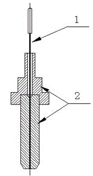
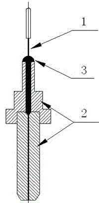
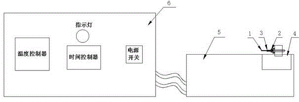
[0056] like Figure 7 to Figure 12 As shown, the automatic gluing equipment for the optical transceiver assembly of the present invention includes a vertical gluing tool 200, a control box 300 and a data monitor 400, the vertical gluing tool 200 includes a tool connector 214, and the The tooling connector 214 is provided with a fixing frame 202, an...


PUM


Abstract

The invention discloses equipment and a method for the automatic glue baking of an optical transceiver assembly, which belong to the field of optical communication device manufacturing. According to the equipment for automatic glue baking, a programmable logic controller (PLC) is arranged in a control cabinet, a vertical glue baking tool is connected with and is controlled by the PLC, and a data monitor is connected with the PLC. The method for automatic glue baking comprises the steps of: 1, fixing a glue injection tail handle and an optical cable; 2, connecting a heating rod and a temperature sensing rod onto to a tool connector; 3, starting the tool connector, setting a temperature control curve, and controlling the heating of the heating rod; 4, using a controller to judge according to the signal, if the temperature is normal, entering step 5; and 5, operating the PLC to complete the temperature control curve, thermally insulating to a preset time, and stopping the heating. With the equipment and the method for automatic glue baking, the heat transfer loss which is generated by the separation of a heating block from a solidification board is eliminated, so the AB glue is solidified during different temperature phases, and the internal stress which is generated by high temperature solidification is eliminated; and the whole solidification process is automatically monitored, fully digitalized and controlled.

Description

technical field [0001] The invention relates to the field of optical communication device manufacturing, in particular to a baking technology for optical transceiver assemblies. Background technique [0002] During the assembly process of the optical transceiver, the core component of the optical transceiver module, some optical fibers are involved in the bonding and fixing: the standard ferrule, the optical fiber and the optical cable are bonded and fixed together with A and B glue, such as figure 1 and figure 2 As shown in the figure, because glue A and B take a long time to cure at natural temperature, it will affect the connection effect of the ferrule with the ferrule and the optical fiber and optical cable, so it needs to be cured quickly without affecting the connection effect. [0003] Existing curing equipment includes: [0004] A: Horizontal curing equipment, such as image 3 As shown in the figure, its working principle: put the glue-injected tail handle 2 on ...

Claims


Application Information

Patent Timeline
IPC IPC(8): G02B6/255G02B6/42
Inventor 胡永忠罗祠富陈先华曾成忠卢勤
Owner FINETOP SCI &TECH
Why Eureka
Try Eureka