Novel optical depolarizer
A depolarizer and optical technology, used in optics, optical components, light guides, etc., can solve the problems of increasing the production cost of hybrid devices and the large size of hybrid devices, and achieve the effects of increasing total energy, reducing volume, and reducing production costs.
- Summary
- Abstract
- Description
- Claims
- Application Information
AI Technical Summary
Problems solved by technology
Method used
Image
Examples
no. 1 example
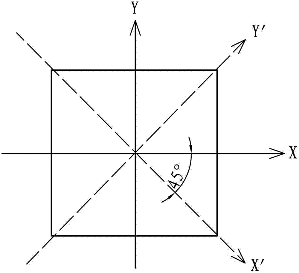
[0050] see Image 6 , the present embodiment has a light-combining isolation component and a depolarization component located at the light exit end of the light-combining isolation component, wherein the light-combining isolation component includes a polarizer 21, an optical rotation plate 22 and a polarizer 23, and the depolarization component includes a birefringent crystal 24, an extension Time slice 25 and birefringent crystal 26 . Wherein, the direction of the optical axis 21a of the polarizer 21 and the direction of the optical axis 23a of the polarizer 23 are viewed as an included angle of 45° along the light transmission direction.
[0051] The birefringent crystal 24 is a light-splitting element, and its optical axis 24a direction forms a certain angle with the top surface of the birefringent crystal 24. For example, if the birefringent crystal 24 is a yttrium vanadate crystal, the angle is 47.85°. The angle at which the ordinary light is separated during transmissio...
no. 2 example
[0080] This embodiment has a light-combining isolation component and a depolarization component, wherein the light-combining isolation component is the same as that of the first embodiment, and will not be described again. The principle diagram of the depolarization component of this embodiment is as follows Figure 10 shown.
[0081] The depolarization assembly is made up of polarization beam splitter 27, time delay plate 28 and polarization beam combiner 29, and wherein polarization beam splitter 27 is used for splitting polarized light, is the splitting element of the present embodiment, and polarization beam combiner 29 uses The light combining element of this embodiment is used to combine the light beams of the two optical paths. The time delay film 28 is located between the polarization beam splitter 27 and the polarization beam combiner 29 , and the time delay film 28 is located on an outgoing optical path of the polarization beam combiner 27 .
[0082] Two beams L51 a...
no. 3 example
[0098] see Figure 11 , the present embodiment has a light combination component and a depolarization component, the light combination component is a birefringent prism 31, and the depolarization component is composed of a birefringent crystal 34 as a light splitting element, a time delay plate 35, and a birefringent crystal 36 as a light combination element , the structure and working principle of the depolarization component are the same as those of the first embodiment, and will not be repeated here.
[0099] The birefringent prism 31 has two crystals 32, 33, wherein the optical axis of the crystal 32 and the optical axis of the crystal 33 are perpendicular to each other, that is, the optical axis of the crystal 32 and the optical axis of the crystal 33 form an included angle of 90°. And the projection of the optical axis of the birefringent crystal 34 on the exit surface of the crystal 33 forms an included angle of 45° with the optical axis of the crystal 33 . The birefri...
PUM
 Abstract
Description
Claims
Application Information
 - R&D
- Intellectual Property
- Life Sciences
- Materials
- Tech Scout
- Unparalleled Data Quality
- Higher Quality Content
- 60% Fewer Hallucinations
Browse by: Latest US Patents, China's latest patents, Technical Efficacy Thesaurus, Application Domain, Technology Topic, Popular Technical Reports.
© 2025 PatSnap. All rights reserved.Legal|Privacy policy|Modern Slavery Act Transparency Statement|Sitemap|About US| Contact US: help@patsnap.com


