Feed device for processing deep holes

A feeding device and deep hole technology, which is applied in the field of feeding device and deep hole processing, can solve the problems of complex structure of the feeding system, affecting processing stability, high manufacturing cost, etc., to improve safety and structure Simple, long-lasting effect

Inactive Publication Date: 2012-11-07
TAIZHOU LIPENG AUTOMATION CONTROL EQUIP
View PDF1 Cites 1 Cited by
  • Summary
  • Abstract
  • Description
  • Claims
  • Application Information

AI Technical Summary

Problems solved by technology

[0004] The above-mentioned feed system for deep hole processing uses compressed air to drive the cylinder as the driving power, and controls the flow rate of the compressed air through various air valves to control the feed speed. The feed is relatively stable. When the drill bit is worn, the drill bit The feed speed will be reduced to avoid damage to the drill bit, but the structure of the feed system for deep hole machining is relatively complex, the manufacturing cost is high, and the drill bit is continuously fed and processed, which makes it difficult to remove chips and affects the stability of processing

Method used


Image

  • Feed device for processing deep holes
  • Feed device for processing deep holes
  • Feed device for processing deep holes

Examples


Embodiment 1

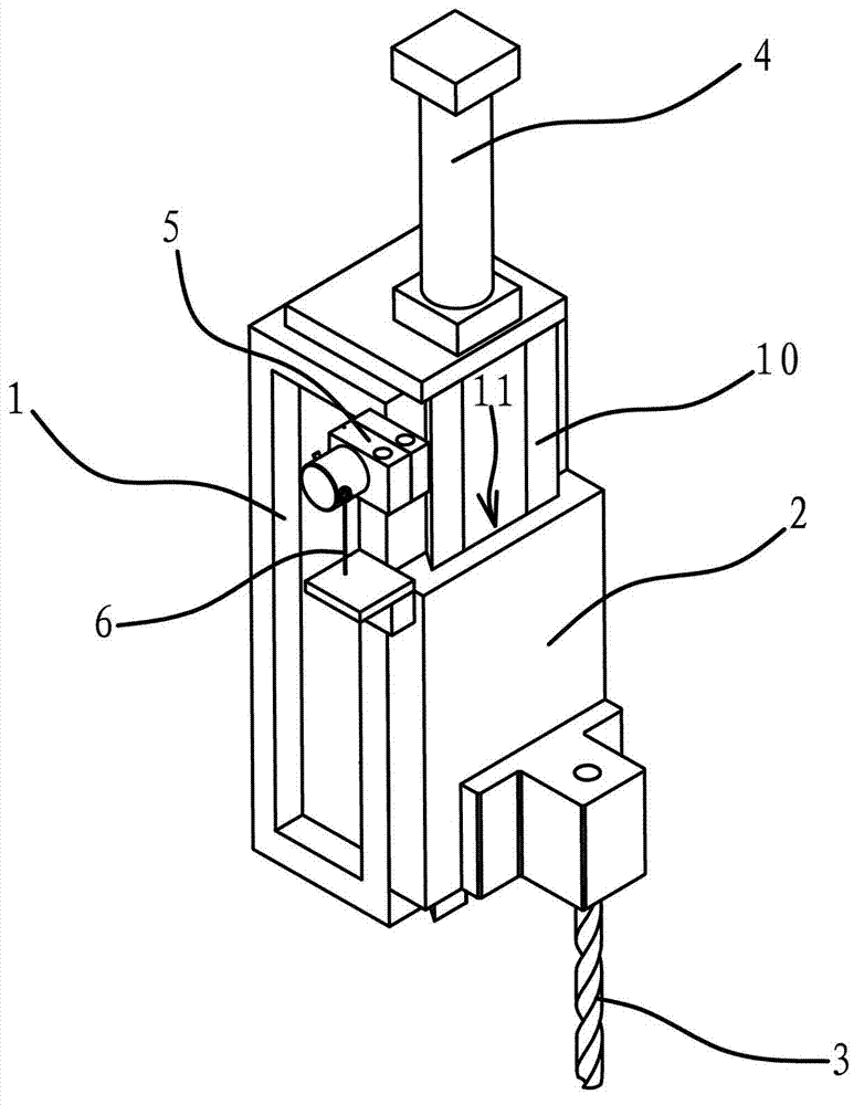
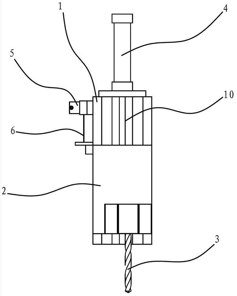
[0038] like figure 1 , 2 , shown in 8, a kind of feeding device of deep hole machining, comprises frame 1, is provided with motion slide block 2 and oil cylinder 4 on frame 1, and one end of motion slide block 2 is fixedly connected with the piston rod of oil cylinder 4, The other end of the moving slider 2 is connected with a cutting tool 3; the frame 1 is also provided with a guide rail-10, the cross-sectional shape of the guide rail-10 is a dovetail groove shape, and the inner end surface of the moving slider 2 has a matching guide rail-10. Chute one 11, guide rail one 10 and chute one 11 are embedded.

[0039] The feeding device also includes a control device, the control device includes a controller, an encoder 5 and a wire rope 6, the encoder 5 is fixed on the frame 1, and one end of the wire rope 6 is connected with the moving slider 2, and on the rotating shaft of the encoder 5 A spring is provided, and the other end of the wire rope 6 is connected with the spring on...

Embodiment 2

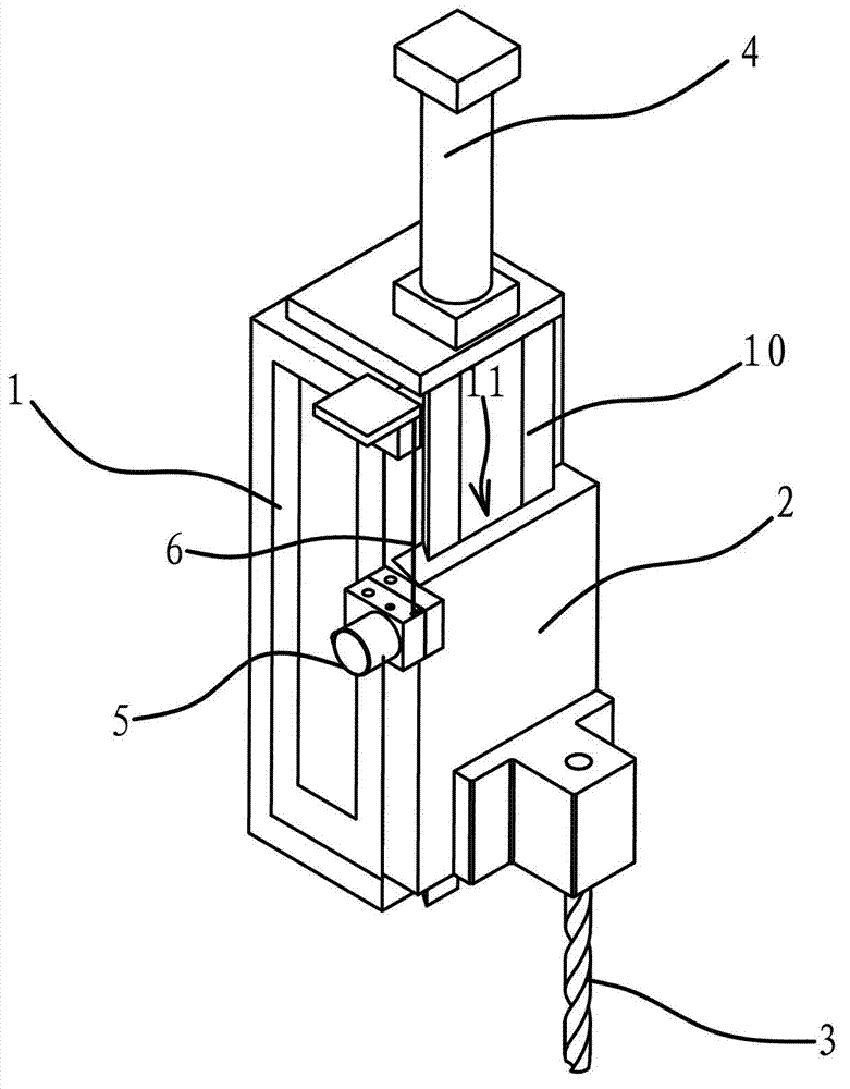
[0044] The structure and principle of this embodiment are basically the same as that of Embodiment 1, the difference is that: image 3 As shown, the control device includes a controller, an encoder 5 and a wire rope 6, the encoder 5 is fixed on the moving slider 2, one end of the wire rope 6 is connected with the frame 1, and the rotating shaft of the encoder 5 is provided with a The other end of the wire rope 6 is connected with the spring on the rotating shaft, the encoder 5 is installed on the motion slider 2, and one end of the wire rope 6 is connected with the frame 1, and the exit position is recorded by the wire rope 6 and the encoder 5. The withdrawal position of the moving slider 2 can be read out with relatively high accuracy, and the movement of the moving slider 2 to any position can be read and the position can be read, which has the advantage of more convenient installation.

Embodiment 3

[0046] The structure and principle of this embodiment are basically the same as that of Embodiment 1, the difference is that: Figure 4 As shown, the control device includes a controller, an encoder 5 and a steel bar 7, the encoder 5 is fixed on the frame 1, the rotating shaft of the encoder 5 is fixedly connected with a turntable-8, and on the frame 1 Also be provided with rotating disk two 9, one end of steel bar 7 links to each other with described motion slide block 2, and rotating disk one 8 and rotating disk two 9 are symmetrically arranged on the both sides of steel bar 7 and all abut against steel bar 7, in motion slide During the translation process of the block 2, the rigid bar 7 can be driven to move. Since the first turntable 8 and the second turntable 9 are symmetrically arranged on both sides of the steel bar 7 and are all abutted against the rigid bar 7, through the rigid bar 7 and the turntable one 8 and the The friction between the two turntables 9 drives the ...


PUM


Abstract

The invention provides a feed device for processing deep holes and belongs to the technical field of machine tool components. The device solves the problems that prior feed devices for processing deep holes are complex in structure and poor in processing stability. The feed device comprises a rack and a control device, wherein a moving sliding block is arranged on the rack, one end of the moving sliding block is connected with a first driving member, the other end of the moving sliding block is connected with a cutter, the first driving member can drive the moving sliding block to make a translational motion, the control device can control the first driving member to drive the moving sliding block to make a multiple reciprocating translational motion, and when the first driving member drives the moving sliding block to translate to a prior translation exit position, the control device enables the first driving member to drive the moving sliding block, so that the high-speed feed motion is changed to a low-speed feed motion. The feed device has the advantages of being simple in structure and good in processing stability.

Description

technical field [0001] The invention belongs to the technical field of machine tool components, and relates to a feeding device, in particular to a feeding device for deep hole processing. Background technique [0002] When the workpiece needs to be drilled, a drilling machine is generally used to drill the workpiece. During processing, the workpiece is fixed on the worktable of the drilling machine, the main movement is through the rotation of the drill bit, and the axial movement of the drill bit is the feed movement. Thereby drilling the workpiece. The processing accuracy of the existing drilling machine is not high, especially when processing deep holes, the drill bit is likely to have a large friction with the hole wall, so that the drill bit is easily stuck in the processing hole, causing damage to the drill bit, and the chips are not easy to discharge. [0003] In order to solve the problems existing in the existing drilling machine, people have carried out various d...

Claims


Application Information

Patent Timeline
IPC IPC(8): B23B47/22B23Q15/013B23B41/02
Inventor 李鹏
Owner TAIZHOU LIPENG AUTOMATION CONTROL EQUIP
Why Eureka
Try Eureka