Rainwater drainage ditch
A drainage ditch and rainwater technology, applied in drainage structures, water/sewage treatment, water/sludge/sewage treatment, etc., can solve problems such as stagnation on rough surfaces, affecting cross-flow sections, rough inner walls, etc., and achieve smooth inner walls Good hydraulic flow, reduced maintenance costs, and reduced sediment deposition
- Summary
- Abstract
- Description
- Claims
- Application Information
AI Technical Summary
Problems solved by technology
Method used
Image
Examples
Embodiment 1
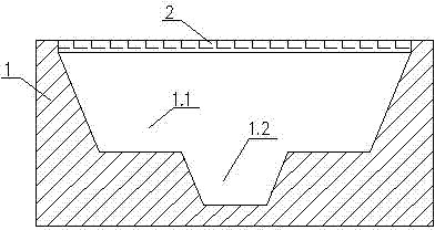
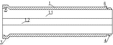
[0027] Embodiment 1: see attached figure 1 , 2 , the rainwater drainage ditch of the present invention comprises the upper large isosceles inverted trapezoid 1.1 of prefabricated concrete and the lower isosceles inverted trapezoid 1.2, and the compound inverted trapezoidal cross-section drainage ditch main body 1 connected to the upper and lower sides in the same direction. 45°~75°, the section ratio of the upper, lower, and lower trapezoids is about 3:1, and the upper part is a large inverted trapezoid 1.1 with a water inlet cover 2. The axial ends of the prefabricated concrete drainage ditch and the rainwater ditch respectively have a flared socket 3 and a tapered insertion section 4 to form a socket connection structure, which is used for socket assembly and connection. The inner peripheral surface of the flared socket 3 has an outwardly protruding annular card slot 5, and the tapered insertion section 4 has a concave annular card slot 6 at the tapered rear end of the oute...
Embodiment 2
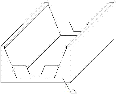
[0028] Example 2: see image 3 , 45. As mentioned above, in the drainage ditch along the drainage water flow direction, the interval (the length depends on the mud and sand carried in various places, such as 30-40 meters) is set between the two-section rainwater ditches with an elevation lower than (such as 200 mm~300mm) rainwater The sedimentation tank 9 at the bottom of the water channel, the lifting basket 7 with the same shape as the sedimentation tank is placed in the sedimentation tank, and fits on the sedimentation tank inner wall, and the top is provided with a lifting hook 8, which is convenient for cleaning. A small amount of pollutants deposited in the lower inverted trapezoid 1.2 are washed into the sedimentation tank 9 with the flow of water, and are removed and discharged by regularly lifting the lifting basket 7 to achieve regular desilting. It is also possible to perforate the side wall and / or bottom surface of the basket 7 to play the role of water filtration...
Embodiment 3
[0030] Embodiment 3: see Figure 5 , as mentioned above, wherein the water inlet cover plate 2 adopts a small width (narrow) structure, and between the narrow water inlet cover plate and the wide middle area of the upper mouth of the rainwater channel, there is a figure-eight connection transition section 11. This structure is mainly used in relatively concealed water inlets, and through the eight-shaped diffusion energy dissipation, the hydraulic conditions of the fall are improved to reduce the scouring force of the rainwater inlet.
PUM
 Abstract
Description
Claims
Application Information
 - R&D
- Intellectual Property
- Life Sciences
- Materials
- Tech Scout
- Unparalleled Data Quality
- Higher Quality Content
- 60% Fewer Hallucinations
Browse by: Latest US Patents, China's latest patents, Technical Efficacy Thesaurus, Application Domain, Technology Topic, Popular Technical Reports.
© 2025 PatSnap. All rights reserved.Legal|Privacy policy|Modern Slavery Act Transparency Statement|Sitemap|About US| Contact US: help@patsnap.com


