Rotary compressor and its manufacturing method

A technology of a rotary compressor and a manufacturing method, which is applied in the directions of rotary piston machinery, rotary piston pump, mechanical equipment, etc., can solve the problems of high production cost of sliding vanes and pistons, poor impact resistance, and high operating pressure, and achieves high resistance to Strong impact ability, good wear resistance, and the effect of improving reliability

Inactive Publication Date: 2012-11-07
GUANGDONG MEIZHI COMPRESSOR
View PDF11 Cites 7 Cited by
  • Summary
  • Abstract
  • Description
  • Claims
  • Application Information

AI Technical Summary

Problems solved by technology

Especially for some refrigerants, such as R401A, CO 2 etc., the operating pressure in the compressor is high, and the pressure difference between the low-pressure chamber 14a and the high-pressure chamber 14b of the compression chamber is large, which is more likely to cause wear and tear, and the service life is shorter
[0005] At present, the commonly used material for sliding vanes is nitrided stainless steel or high-speed steel, and the common material for pistons is cast iron, but some rare metals are added to cast iron, so the production cost of sliding vanes and pistons is relatively high
[0006] Chinese Patent Document No. CN1085992A disclosed a blade for a rotary compressor on 1994.04.27, and a Chinese Patent Document No. CN101265909A disclosed a ceramic sliding vane for a hermetic rotary compressor on 2008.09.17. Although the ceramic material has high hardness and low price, it is easy to break when it is impacted because the ceramic material is relatively brittle and has poor impact resistance.

Method used


Image

  • Rotary compressor and its manufacturing method
  • Rotary compressor and its manufacturing method
  • Rotary compressor and its manufacturing method

Examples


no. 1 example

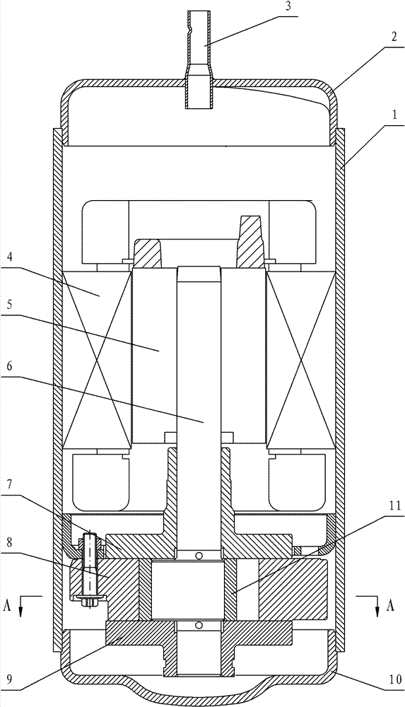
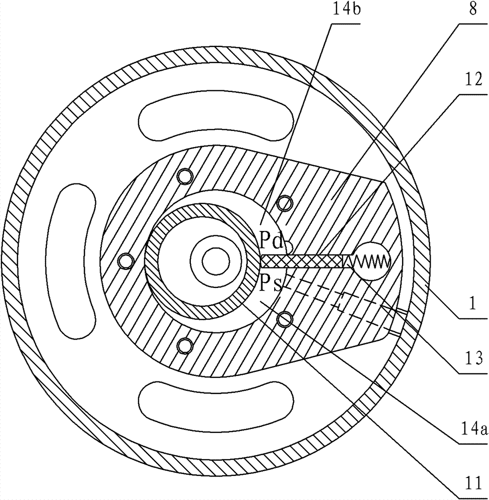
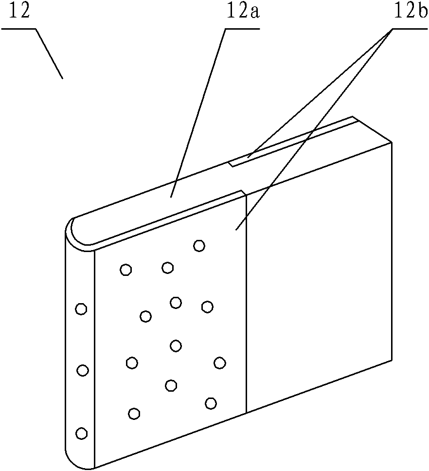
[0028] see image 3 , the rotary compressor includes a motor and a compression mechanism arranged in the housing, the compression mechanism includes a cylinder 8 with a compression cavity, a piston 11 that rotates eccentrically in the compression cavity, and a slide plate 12 is also arranged on the cylinder 8 Slide groove 13, one end of slide 12 abuts against the outer circumference of piston 11, slide 12 includes slide metal base 12a, and slide ceramic composite layer 12b arranged on slide metal base 12a; slide ceramic composite layer 12b is arranged on one side, both sides or the tip of the slider metal base 12a. The metal matrix 12a of the sliding vane is a cast iron matrix or a steel matrix. The slider ceramic composite layer 12b includes a porous slider ceramic layer and metal embedded in the slider ceramic layer. The sliding ceramic layer is an aluminum oxide layer, a silicon oxide layer or a zirconium oxide layer.

[0029] When making, first prepare a porous sliding ...

no. 2 example

[0031] see Figure 4-Figure 5 , The piston 11 in this embodiment includes a piston metal base 11a, and a piston ceramic composite layer 11b disposed on the piston metal base 11a; the piston ceramic composite layer 11b is disposed on the inner or outer circumference of the piston metal base 11a. The metal matrix 11a of the piston is a cast iron matrix or a steel matrix. The piston ceramic composite layer 11b includes a porous piston ceramic layer 11c and metal embedded in the piston ceramic layer 11c. The piston ceramic layer 11c is an alumina layer, a silicon oxide layer, a zirconia layer, a silicon carbide layer or a zirconia layer.

[0032] During production, at first prepare the porous piston ceramic layer 11c as required, and the wall degree of the piston ceramic layer 11c is 0.5-10mm; then place the piston ceramic layer 11c on the core 15 in the mold 18, and then cast the liquid metal 17 into the In the casting mold 18, a part of the liquid metal 17 enters the piston ce...


PUM


Abstract

Disclosed are a rotary compressor and its manufacturing method. The rotary compressor comprises a motor and a compressing mechanism which are arranged inside a housing. The compressing mechanism comprises a cylinder with a compression chamber and a piston which rotates eccentrically inside the compression cavity. The cylinder is also provided with a sliding plate groove for holding a slide plate. One end of the slide plate is propped to the periphery of the piston. The slide plate comprises a slide plate metal matrix and a slide plate ceramic composite layer arranged on the slide plate metal matrix. The slide plate ceramic composite layer is arranged at one side, two sides or distal end of the slide plate metal matrix. The slide plate metal matrix is a cast iron matrix or steel matrix. The slide plate ceramic composite layer comprises a porous slide plate ceramic layer and metal embedded in the slide plate ceramic layer. The slide plate ceramic layer is an alumina layer, oxygen ambient silica layer or zirconia layer. The rotary compressor provided by the invention has characteristics of simple and reasonable structure, flexible operation, low manufacturing cost, high surface hardness, good wear resistance, good impact toughness and long service life.

Description

technical field [0001] The invention relates to a rotary compressor, in particular to a rotary compressor and a manufacturing method thereof. Background technique [0002] Compressors are important components of household appliances such as air conditioners and refrigerators that use the refrigeration cycle system to work. Utilize its moving parts driven by the motor, such as a rotary compressor, to convert mechanical energy into pressure energy, realize the compression of the refrigerant in the cylinder of the compressor, and discharge the compressed refrigerant into the refrigeration cycle. [0003] see Figure 1-Figure 2 , is a structural schematic diagram of an existing rotary compressor. Such as figure 1 As shown, the compressor is composed of a compression mechanism and a motor arranged in a cylindrical main casing 1 . After the main casing 1 is closed by the upper casing 2 and the lower casing 10, it constitutes the casing of the compressor. In the casing of the ...

Claims


Application Information

Patent Timeline
Patent Type & Authority Applications(China)
IPC IPC(8): F04C18/356B22D19/08
Inventor 龙春仙
Owner GUANGDONG MEIZHI COMPRESSOR
Why Eureka
Try Eureka