

Test platform for steel-rail milling and grinding machine
A technology for a rail milling and grinding car and a test bench, applied in the field of test platforms, can solve the problems of high cost, complex test structure, huge test site, etc., and achieve the effects of low cost, perfect function and simple structure
- Summary
- Abstract
- Description
- Claims
- Application Information
AI Technical Summary
Problems solved by technology
Method used
Image

Examples
Embodiment Construction
[0013] A specific implementation of a rail milling and grinding car test bench will be described in detail below in conjunction with the accompanying drawings.
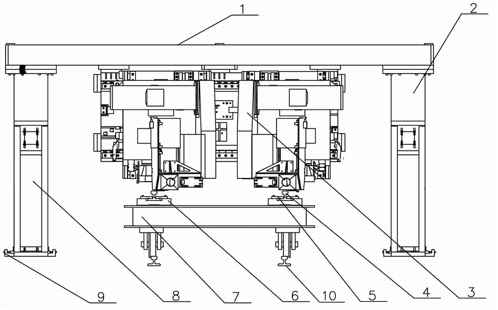
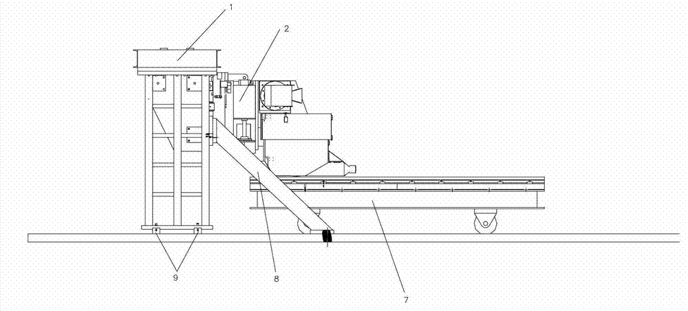
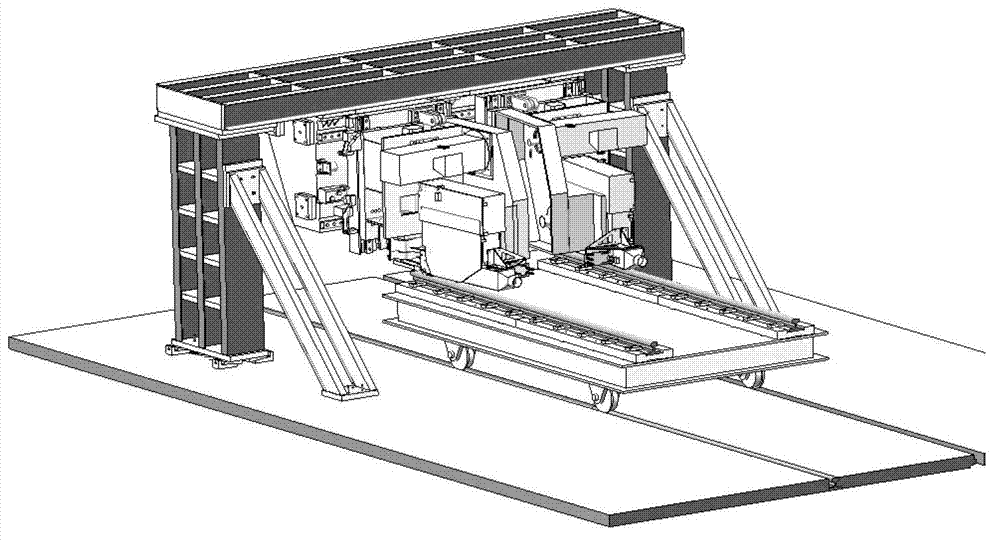
[0014] like figure 1 , 2 , 3. A rail milling and grinding car test bench includes a test platform frame and a feeding device. The test platform frame includes a beam 1, a support 2, a side support frame 8 and a first adjustment pad iron 9. The feeding device includes a rail test piece 4, a weight 5, a guide rail car 7 and a second adjustment pad iron 6.
[0015] The rail milling and grinding vehicle 3 is hung upside down on the beam 1, the first adjustment pad 9 is fixed to the ground through anchor bolts, the support 2 is installed on the first adjustment pad 9, and the rail test piece 4 is fixed to the second adjustment pad through a pressure block. On the pad iron 6, the second adjustment pad iron 6 is integrally fixed on the guide rail car 7.
[0016] The rail milling and grinding car 3 has three kinds of worki...
PUM
 Abstract
Description
Claims
Application Information