

Device and method for detecting reducibility of iron ore
A technology for measuring devices and iron ore powder, which is applied to measuring devices, instruments, scientific instruments, etc., can solve the problems of many iron ores, many harmful gases, complicated test process, etc., and achieve good consistency, good safety, and easy operation simple effect
Inactive Publication Date: 2012-11-07
UNIV OF SCI & TECH BEIJING
View PDF7 Cites 11 Cited by
- Summary
- Abstract
- Description
- Claims
- Application Information
AI Technical Summary
Problems solved by technology
[0005] Aiming at the deficiencies in the prior art that use the national standard GB / T13241-91 method to study iron ore reducibility, the test process is complicated, requires a large amount of iron ore, and produces more harmful gases during the test process, the present invention provides an iron ore reduction It is a device and method for property determination. The device is compact in layout, simple in operation and easy to master. The amount of sample and gas required for the test is far less than that of the national standard GB / T13241-91
Method used
View moreImage
Smart ImageViewing Examples

Examples
specific Embodiment 1
[0028] Take 200g of three iron ore samples (sinter, pellets and lump ore) respectively, with a particle size of 10-12.5mm, put them in a drying oven, and dry them at 105°C for 120min. After cooling, use a sealed The sample preparation machine is crushed to below 200 mesh, and then weighs 50±1mg of the sample for use.
Login to View More PUM
 Abstract
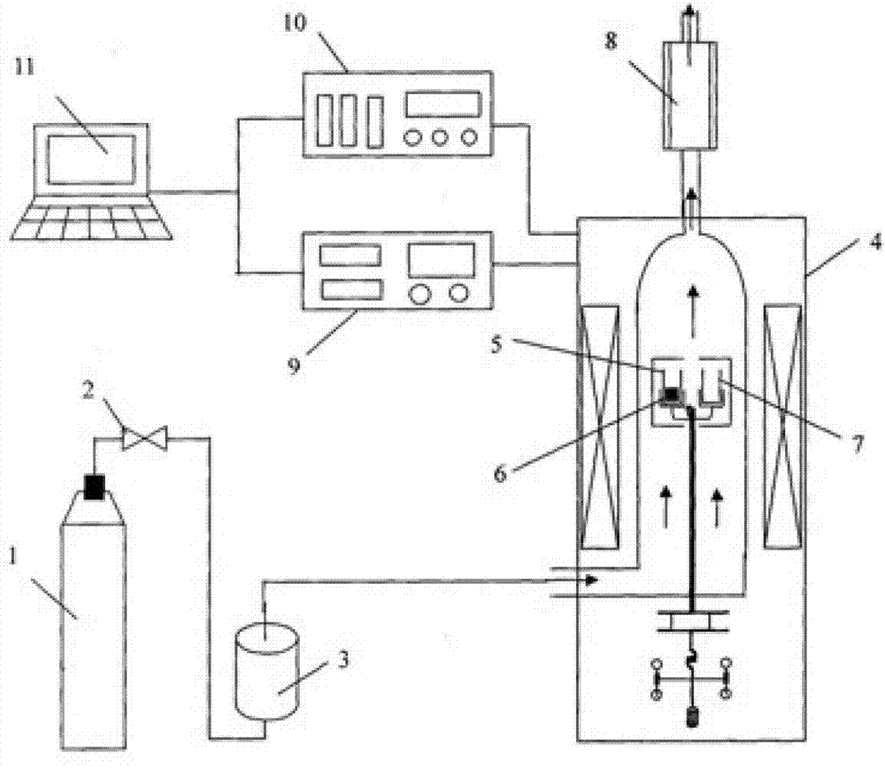
The invention provides a device and a method for detecting reducibility of iron ore. The device comprises an air supply system, a thermogravimetric scale, a tail gas treatment system, a temperature control system, a gas control system and a compute data processing system. In the test process, a test sample 5 is placed in a crucible; a contrastive empty crucible is placed at the other end, and temperature is raised according to a predetermined temperature raising system. The method comprises the following steps: detecting by using a differential thermal scale device mainly based on a thermogravimetry theory; collecting temperature data and quality data in real time in the reaction process; and recording a thermogravimetric curve in the test where weight changes along with the temperature. The device provided by the invention is convenient to operate, small in volume and good in safety because harmful gases produced in the reduction process are discharged after being treated by the tail gas treatment system.
Description
technical field [0001] The invention relates to a device and a method for testing iron ore, more specifically to a device and a method for measuring the reducibility of iron ore. Background technique [0002] Reduction performance indicates the ease of removing iron-bound oxygen from iron ore with a reducing agent. The calculation of the degree of reduction is based on the state of ferric iron (that is, it is assumed that all the iron in the iron ore is Fe 2 o 3 The form exists, and these Fe 2 o 3 The oxygen in it is counted as 100%), and the degree of deoxygenation achieved after reduction for a certain period of time is expressed in mass percent. The reducibility of iron ore is usually studied by the national standard GB / T13241-91 "Measurement method for reducibility of iron ore". The experimental operation is complicated, the amount of iron ore required is large, and the human factors in the test process are greatly affected. [0003] CN201464316 discloses a novel i...
Claims
Login to View More Application Information
Patent Timeline
 IPC IPC(8): G01N5/00
Inventor国宏伟苏步新张建良左海滨刘征建闫炳基傅源荻
OwnerUNIV OF SCI & TECH BEIJING