Stator in an electric motor

An electric motor and stator technology, applied in electric components, electrical components, electromechanical devices, etc., can solve the problems of increasing torque fluctuation, torque loss, magnetic flux loss, etc., to reduce magnetic flux loss, simplify manufacturing, reduce The effect of small flux resistance

Inactive Publication Date: 2012-11-07
ROBERT BOSCH GMBH
View PDF8 Cites 3 Cited by
  • Summary
  • Abstract
  • Description
  • Claims
  • Application Information

AI Technical Summary

Problems solved by technology

However, there are at least partial seams in between which cause flux and torque loss...

Method used


Image

  • Stator in an electric motor
  • Stator in an electric motor
  • Stator in an electric motor

Examples


Embodiment Construction

[0026] The same components are identified in the figures with the same reference numerals.

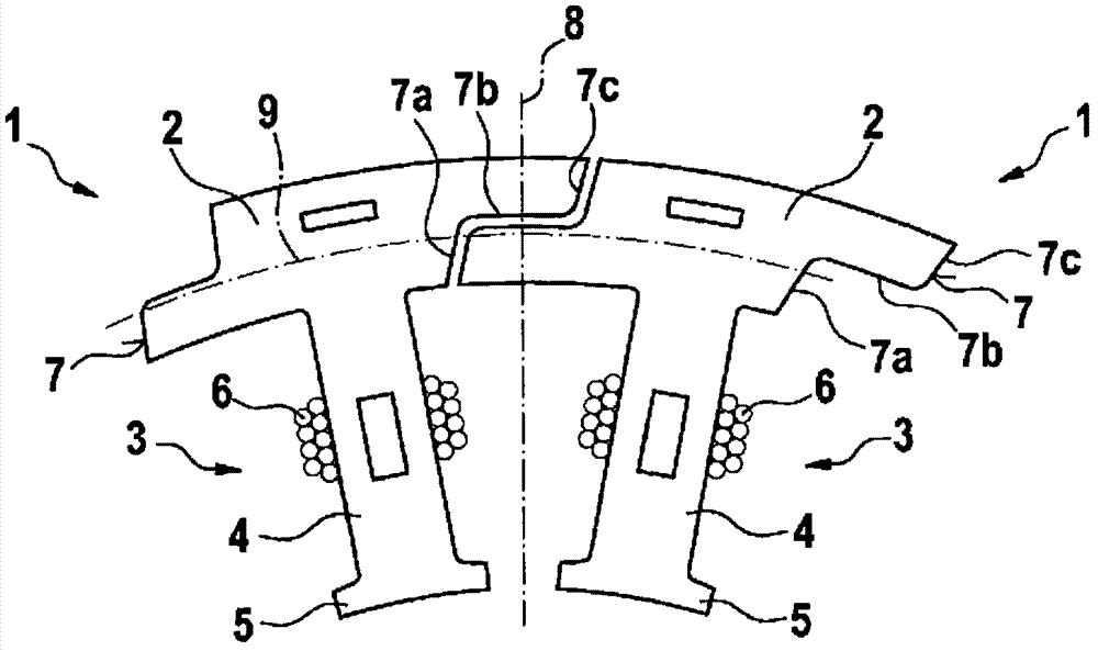
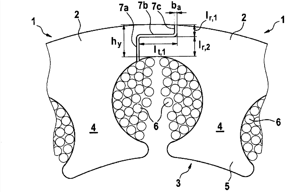
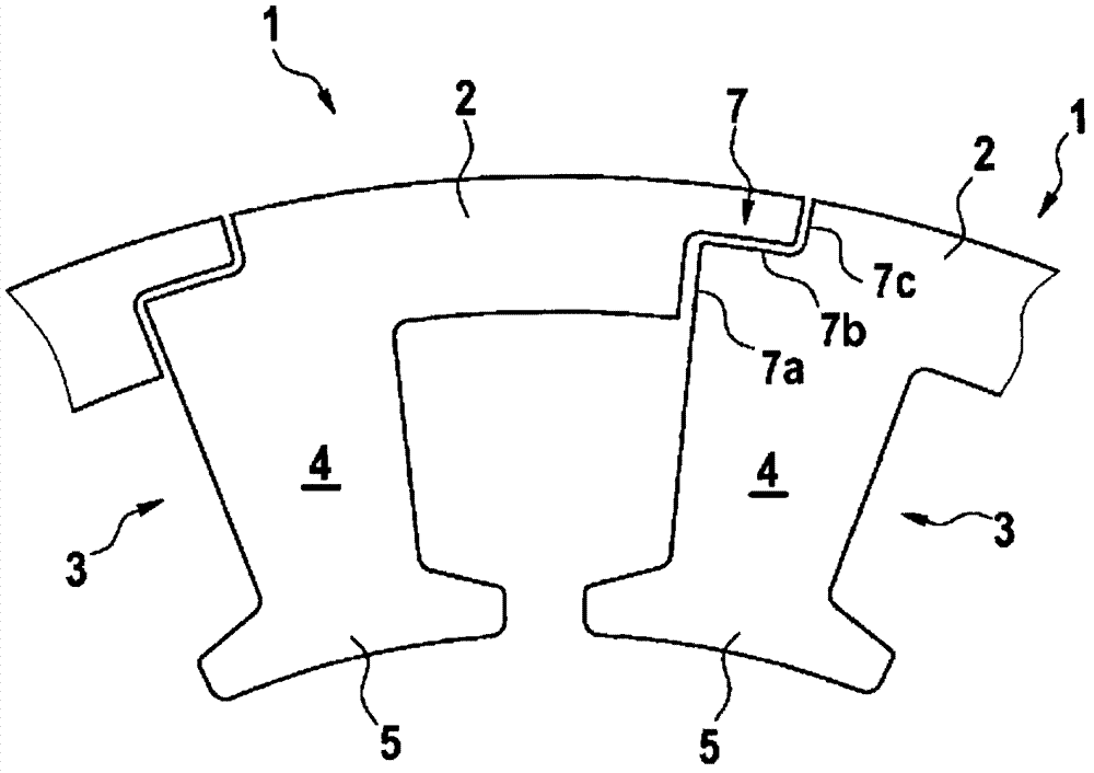
[0027] exist figure 1 Two adjacent tooth segments 1 of a stator for an EC inner rotor electric motor are shown in . Each tooth segment 1 comprises a tangentially extending yoke segment 2 on the radially outer side, and supporting teeth 3 integrally formed with the yoke segment 2 , extending radially inward and respectively accommodating energizable coils 6 . A plurality of such tooth segments 1 are distributed on the circumference and jointly form a continuous stator ring.

[0028] The bearing tooth 3 consists of a radially facing base body 4 and a radially inner tooth crown 5 , wherein a coil 6 is wound around the side surface of the base body 4 , the tooth crown 5 being tangentially wider than the base body 4 and Form the pole shoe. The radial inner side of the tooth crown 5 is arranged directly adjacent to the rotor surrounded by the stator, wherein an annular air gap exists betw...


PUM


Abstract

The invention relates to a stator in an electric motor comprising a plurality of teeth segments forming a stator ring. Each tooth segment comprises a yoke segment and support teeth for receiving coils carrying electric current. The peripheral front side of a yoke segment forms a contact surface with at least one straight-lined contact surface section which forms an angle in relation to the radial line.

Description

technical field [0001] The invention relates to a stator in an electric motor according to the general concept of claim 1 , in particular for an electronically commutated synchronous machine. Background technique [0002] From patent document DE 10 2004 043 424 A1 an inner rotor motor with a stator is known, which consists of a radially outer stator ring and a plurality of support teeth distributed uniformly around the circumference and extending radially inwards for receiving energizable coils constitute. The stator ring is composed of individual tooth segments, each of which is formed by an overlapping section or yoke arc section, with which the radially extending support teeth adjoin the overlapping section or yoke arc section in one piece. After assembly, the yoke segments form the stator ring of the stator, which is formed continuously in the tangential direction. [0003] In order to connect the yoke arc segments, a knob-shaped protrusion or a corresponding groove is...

Claims


Application Information

Patent Timeline
IPC IPC(8): H02K1/14
CPCH02K1/148
Inventor M·巴特K-J·罗特A·诺伊鲍尔A·埃韦特
Owner ROBERT BOSCH GMBH
Why Eureka
Try Eureka