Composite casing pipe restrained reinforced concrete column

A technology of reinforced concrete columns and composite sleeves, which is applied in the direction of columns, pier columns, pillars, etc., can solve the problems of hollowing out between steel pipes and concrete, large differences in material properties, and increased use costs, so as to improve bearing capacity and ductility. The effect of high axial bearing capacity and good bearing capacity ductility

Inactive Publication Date: 2012-11-14
HUNAN UNIV
View PDF7 Cites 16 Cited by
  • Summary
  • Abstract
  • Description
  • Claims
  • Application Information

AI Technical Summary

Problems solved by technology

[0007] At present, the main problems of the confined concrete composite columns made of steel pipes or FRP as the restraining parts are: the material price is high; the fire resistance of steel pipe concrete columns and FRP confined concrete columns is poor, and other measures need to be taken to increase the fire resistance limit ; In addition, the material properties of steel pipes and concrete are very different, which easily leads to the separation of steel pipes and concrete. Regular maintenance is required for steel pipe concrete columns during use, which increases the cost of use, etc.

Method used


Image

  • Composite casing pipe restrained reinforced concrete column
  • Composite casing pipe restrained reinforced concrete column
  • Composite casing pipe restrained reinforced concrete column

Examples


Embodiment 1

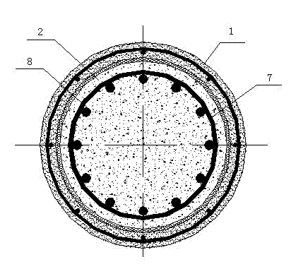
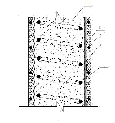
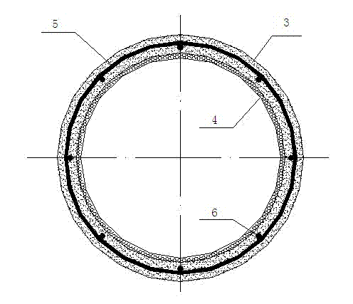
[0033] A composite casing-confined reinforced concrete column such as figure 1 , figure 2 , image 3 As shown, it is characterized in that the composite casing (1) of the reinforced concrete column (2) is a combination of a prefabricated active powder concrete outer casing (3) and an inner casing (4).

[0034] The inner casing (4) is a fiber reinforced plastic (FRP) pipe or steel pipe.

[0035] Fiber reinforced plastic (FRP) inner casing (4) is carbon fiber reinforced plastic (CFRP) pipe, glass fiber reinforced plastic (GFRP) pipe, aramid fiber reinforced plastic (AFRP) pipe, basalt fiber reinforced plastic (BFRP) pipe or hybrid Fiber reinforced plastic (HFRP) pipe.

[0036] The reinforcing bars arranged in the active powder concrete outer casing (3) are closed stirrups (5) and longitudinal reinforcing bars (6).

[0037] The reinforcing bars arranged in the reinforced concrete column (2) are closed stirrups (7) and longitudinal reinforcing bars (8).

Embodiment approach

[0039] First of all, bind the reinforcement cage composed of the longitudinal reinforcement 6 and the closed stirrup 5 in the active powder concrete outer casing, and place it in the mold composed of the outer mold and the inner casing 4 for making the prefabricated active powder concrete outer casing 2; pour the prepared Reactive powder concrete is made into a composite casing 1; the formwork is removed after one day of pouring, and the composite casing 1 is placed in hot water at 90°C for 48 hours of curing; the prefabricated composite casing 1 is transported to the construction site, and Hoisting in place; binding the longitudinal reinforcement 8 and the closed stirrup 7 of the reinforced concrete column 2 in the composite casing 1; supporting the formwork of the reinforced concrete beam 10 and the floor (not shown), binding the steel bars of the beam and the floor, and then Concrete is poured, so that the reinforced concrete column 9 constrained by composite sleeves is form...


PUM

PropertyMeasurementUnit
flexural strengthaaaaaaaaaa

Abstract

The invention discloses a composite casing pipe restrained reinforced concrete column which is characterized in that a composite casing pipe of the reinforced concrete column (2) is a combined body of a precast active power concrete outer casing pipe (3) and a precast active power concrete inner casing pipe (4). The composite casing pipe restrained reinforced concrete column provided by the invention has the characteristics of convenience in construction, low cost, high bearing force, shock-resistant property, obvious fireproof performance, excellent durability and the like, meanwhile, the composite casing pipe restrained reinforced concrete column can be used for saving resources and energy sources, and conforms to the sustainable development requirement.

Description

technical field [0001] The invention mainly relates to the field of building structures in civil engineering, in particular to a composite sleeve restrained reinforced concrete column that can be used as a structural column. Background technique [0002] With the progress of the society and the continuous development of the economy, the modern construction industry has higher and higher requirements for building materials and building structures. The materials and structures must be able to adapt to the development of modern engineering structures to large spans, towering towers, and heavy loads and to withstand harsh conditions. The use environment and durability requirements meet the requirements of modern construction technology industrialization, and have high load-bearing capacity, good deformation capacity, good fire resistance and good performance / cost ratio. In the past 30 years, the emergence and development of new composite materials and composite structures have g...

Claims


Application Information

Patent Timeline
Patent Type & Authority Applications(China)
IPC IPC(8): E04C3/34E04C5/07E04C5/01
Inventor 单波肖岩龚建清
Owner HUNAN UNIV
Why Eureka
Try Eureka