External combustion engine and transmission mechanism thereof

A technology of transmission mechanism and external combustion engine, which is applied in the direction of machine/engine, hot gas variable capacity engine device, mechanical equipment, etc. The effect of long maintenance-free period, low lubrication requirements and easy start-up

Inactive Publication Date: 2012-11-21
杨永顺
View PDF9 Cites 0 Cited by
  • Summary
  • Abstract
  • Description
  • Claims
  • Application Information

AI Technical Summary

Problems solved by technology

[0008] Another object of the present invention is to provide an external combustion engine with a relatively small distance between two cylinders, a compact structure, and low cost, so as to solve the problem that the external combustion engine in the prior art is not compact in structure, high in cost, inconvenient for heating and pressurized technical issues

Method used


Image

  • External combustion engine and transmission mechanism thereof
  • External combustion engine and transmission mechanism thereof
  • External combustion engine and transmission mechanism thereof

Examples


no. 1 example

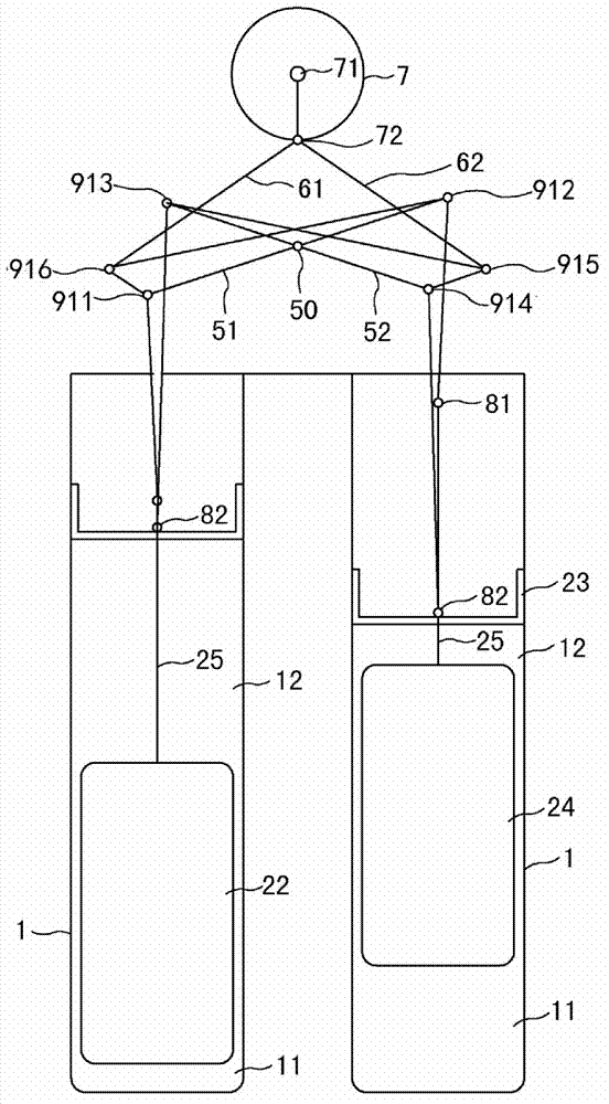
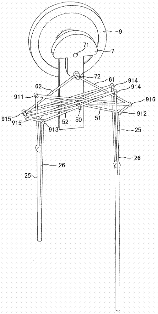
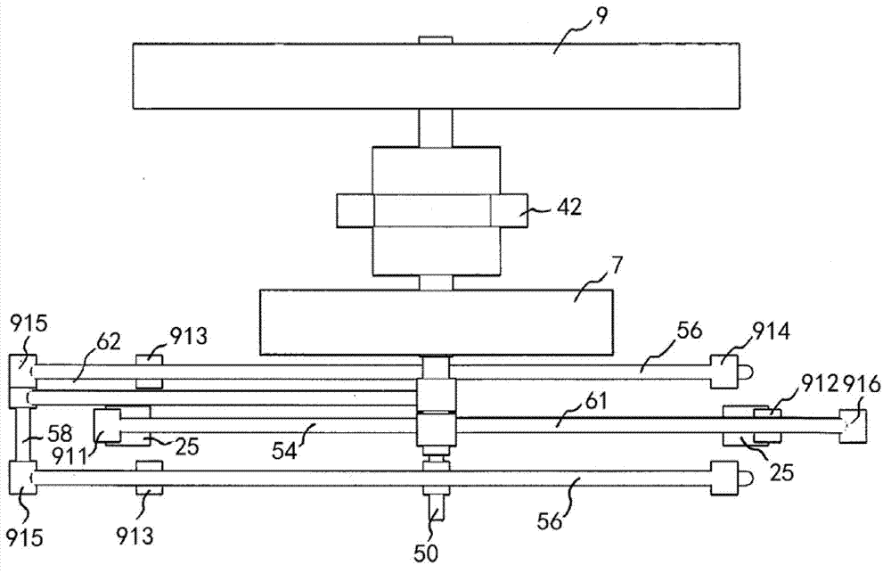
[0028] Such as Figure 1-Figure 5 As shown, the external combustion engine of the first embodiment of the present invention can be divided into three parts: the hot gas assembly, the crankshaft 7 and the transmission mechanism, wherein the transmission device includes two parts: a swing rod group and a connecting rod group.

[0029] 1. Hot air components

[0030] Firstly, the hot gas assembly can be the same as that of the external combustion engine in Document 1.

[0031] Such as figure 1 As shown, the hot gas components are two groups, and each group of hot gas components includes a cylinder 1, a heater, a regenerator and a cooler (not shown in the figure), and each cylinder 1 has an upper and a lower power piston 21, 23 and displacement pistons 22, 24; a cold cavity 12 is formed between the power pistons 21, 23 and the displacement pistons 22, 24, and a hot cavity 11 is formed between the displacement pistons 22, 24 and the cylinder (bottom); the thermal cavity 11 and the...

no. 3 example

[0073] The difference between this embodiment and the first two embodiments lies in the difference in the transmission mechanism. The same parts as the first two embodiments will not be repeated, and the differences will be mainly introduced.

[0074] In this example,

[0075] Such as Figure 7 As shown, the left and right ends of the center swing rod 51 of the swing rod group respectively have a first hinge point 941 and a second hinge point 942 to hinge the upper end of the piston rod 25, while the two ends of the side swing rod 52 have a third hinge point respectively 943 and the fourth hinge point 944 hinge the upper end of the piston rod 26 .

[0076] Wherein, the first hinge point 941 and the second hinge point 942 are equidistant from the pivot shaft 50, and the third hinge point 943 and the fourth hinge point 944 are equidistant from the pivot shaft 50, so as to ensure that the two ends of the swing rod 51, 52 are balanced in force. . In this embodiment, the distanc...


PUM


Abstract

The invention discloses an external combustion engine and a transmission mechanism thereof. The transmission mechanism of the external combustion engine comprises a connecting rod group and an oscillating rod group, wherein the connecting rod group includes a first connecting rod and a second connecting rod, the upper ends of the first connecting rod and the second connecting rod are hinged to a connecting rod neck of a crankshaft of the external combustion, the oscillating rod group includes a central oscillating rod and two side oscillating rods, the two side oscillating rods are symmetrically arranged on two sides of the central oscillating rod, the oscillating plane of the central oscillating rod is parallel to the oscillating planes of the two side oscillating rods, and the central oscillating rod and the side oscillating rods are coaxial with a pivot. The central oscillating rod is provided with a first hinge point and a second hinge point which are used for hinging a piston rod of a replacement piston, and the distance between the first hinge point and the pivot is equal to that between the second hinge point and the pivot. The side oscillating rods are respectively provided with a third hinge point and a fourth hinge point which are used for hinge a piston rod of a power piston, and the distance between the third hinge point and the pivot is equal to that between the fourth hinge point and the pivot. The lower end of the second connecting rod is hinged to a fifth hinge point, on the first side of the pivot, of the side oscillating rods, and the lower end of the first connecting rod is hinged to a sixth hinge point, on the second side of the pivot, of the side oscillating rods. By the transmission mechanism of the external combustion engine, distance between two air cylinders can be shortened.

Description

technical field [0001] The invention relates to an engine, in particular to an external combustion engine and its transmission mechanism. Background technique [0002] The external combustion engine is a closed cycle reciprocating piston heat engine with external combustion. Because it was invented by Stirling in Scotland in 1816, it is also called the Stirling engine, also known as the heat engine. The medium substance (usually high-pressure gas) that transfers energy in the external combustion engine is called working medium, and a certain volume of working medium is filled in one, two, four or more closed cylinders. One end of the cylinder is a hot chamber and the other end is a cold chamber. The working medium is compressed in the low-temperature cold chamber, and then flows into the high-temperature hot chamber to be heated rapidly and expand to do work. The heat brought by the continuous combustion of the fuel in the combustion chamber outside the cylinder or the ext...

Claims


Application Information

Patent Timeline
Patent Type & Authority Applications(China)
IPC IPC(8): F02G1/053
Inventor 杨永顺
Owner 杨永顺
Why Eureka
Try Eureka