Optical fiber watt transducer using reflective quasi-reciprocal light path

A quasi-reciprocal, reflective technology, applied in the direction of electric power measurement, instrumentation, and electric variable measurement through current/voltage, can solve the problems of small dynamic range, high cost, narrow frequency band, etc., and achieve large dynamic range and stability Good, good linearity effect

Inactive Publication Date: 2012-11-21
BEIHANG UNIV
View PDF7 Cites 25 Cited by
  • Summary
  • Abstract
  • Description
  • Claims
  • Application Information

AI Technical Summary

Problems solved by technology

At present, the measurement of voltage and current in the power system mainly uses traditional electromagnetic current or capacitive voltage transformers. With the continuous increase of system voltage levels, traditional electromagnetic and capacitive transformers have exposed a series of serious problems. Disadvantages: (1) The insulation structure of electromagnetic induction transformers is becoming more and more complex, and the cost increases exponentially with the voltage level; (2) The transient response of capacitive transformers is poor; (3) Inherent magnetic saturation, ferromagnetic resonance, Small dynamic range, narrow frequency band, etc.; (4) The analog output of 100V or 5A cannot be directly connected to the computer, which is difficult to meet the development needs of the new generation of power system automation, power digital network, etc.
At present, most of the combined current / voltage transformers connected to the grid for trial operation are block glass optical current sensors based on the Faraday magneto-optic effect and optical voltage transformers based on the Pockels longitudinal electro-optic effect. The sensor head of the current sensor requires precision processing technology, the cost is high, and the linear birefringence formed by the residual stress of the optical glass material itself changes with the change of the ambient temperature; the optical voltage transformer uses crystals, polarizers, wave plates and polarizers, etc. Discrete optical devices, the bonding between discrete devices is difficult to ensure the stability and measurement accuracy of long-term operation

Method used


Image

  • Optical fiber watt transducer using reflective quasi-reciprocal light path
  • Optical fiber watt transducer using reflective quasi-reciprocal light path
  • Optical fiber watt transducer using reflective quasi-reciprocal light path

Examples


Embodiment Construction

[0015] The present invention will be further described in detail with reference to the accompanying drawings and embodiments.

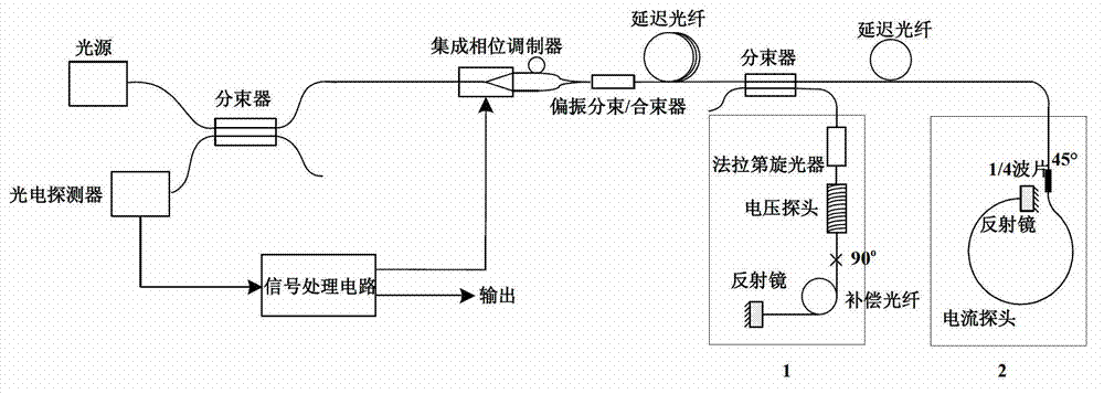
[0016] The present invention is an optical fiber electric power sensor adopting a reflective quasi-reciprocal optical path, and has two implementation schemes, specifically:

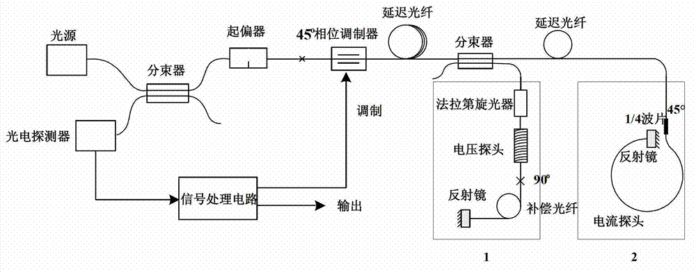
[0017] Such as figure 1 As shown, it is the first implementation of the present invention. A fiber optic electric power sensor using a reflective quasi-reciprocal optical path of the present invention includes a light source, a first beam splitter, a polarizer, a phase modulator, a first delay Optical fiber, second beam splitter, Faraday rotator, voltage probe, compensation fiber, first mirror, second delay fiber, 1 / 4 wave plate, current probe, second mirror and photodetector. Among them: Faraday rotator, voltage probe, compensation fiber and the first reflector constitute the voltage sensitive unit, the specific structure of the voltage probe is that the sensing fiber is evenl...


PUM


Abstract

The invention discloses an optical fiber watt transducer using a reflective quasi-reciprocal light path. Two schemes are provided, wherein one of the schemes is that optical fiber watt transducer comprises a light source, a first beam splitter, a polarizer, a phase modulator, a first delay optical fiber, a second beam splitter, a Faraday rotator, a voltage probe, a compensation optical fiber, a first reflector, a second delay optical fiber, a 1 / 4 wave plate, a current probe, a second reflector and a photoelectric detector; the another scheme is that the optical fiber watt transducer comprises the light source, the first beam splitter, an integrated phase modulator, a polarization beam splitter / combiner, the first delay optical fiber, the second beam splitter, the Faraday rotator, the voltage probe, the compensation optical fiber, the first reflector, the second delay optical fiber, the 1 / 4 wave plate, the current probe, the second reflector and the photoelectric detector. The optical fiber watt transducer disclosed by the invention has good capacity to resist environmental interferences such as temperature and vibration, is good in stability, low in noises, large in dynamic range and good in linearity, and can realize closed-loop detection.

Description

technical field [0001] The invention relates to an optical fiber electric power sensor adopting a reflective quasi-reciprocal optical path, belonging to the technical field of optical fiber sensing. Background technique [0002] The electric power industry is the basic industry of the national economy and plays a pivotal role in the construction of the national economy. In recent years, with the rapid development of my country's industry, the demand for electric energy has greatly increased. However, due to the unbalanced regional economic development in my country, the eastern coast is an industrial-intensive area, but the lack of energy has caused a serious shortage of electricity; However, the energy resources are relatively abundant, and most of the hydropower and coal power resources are located in the western mountainous areas. In response to this situation, the country has proposed a strategy of west-to-east power transmission, and the east-west span of our country is...

Claims


Application Information

Patent Timeline
Patent Type & Authority Applications(China)
IPC IPC(8): G01R21/06G01R19/00G01R15/24
Inventor 王夏霄冯秀娟于佳李传生李立京李彦张晞邬战军
Owner BEIHANG UNIV
Why Eureka
Try Eureka