Method for improving uniformity of shallow trench isolation chemical-mechanical planarization

A chemical mechanical and shallow trench technology, which is applied in the manufacture of electrical components, circuits, semiconductors/solid-state devices, etc., can solve the problems of silicon oxide abrasion, elimination, and reduction of CMP uniformity

Active Publication Date: 2012-11-21
江苏中科汉韵半导体有限公司
View PDF2 Cites 7 Cited by
  • Summary
  • Abstract
  • Description
  • Claims
  • Application Information

AI Technical Summary

Problems solved by technology

Due to the large silicon oxide thickness drop ( figure 1 The height difference of the top of the silicon oxide layer 3 is, for example, ), in the STI CMP process, this thickness difference cannot be eliminated directly by the CMP process, and will be inherited until the end of the CMP process, causing part of the silicon oxide in the shallow trench to be worn away, forming a dishing defect, and causing the electrical performance of the device drop, or even yield reduction, see attached figure 2
[0004] All in all, when the current HDP-CVD fills the STI with high AR, the large silicon oxide thickness difference reduces the CMP uniformity and causes device defects

Method used


Image

  • Method for improving uniformity of shallow trench isolation chemical-mechanical planarization
  • Method for improving uniformity of shallow trench isolation chemical-mechanical planarization
  • Method for improving uniformity of shallow trench isolation chemical-mechanical planarization

Examples


Embodiment 1

[0021] Figure 3 to Figure 5 A schematic cross-sectional view showing various steps of vertical ion implantation to increase silicon oxide removal rate according to Embodiment 1 of the present invention.

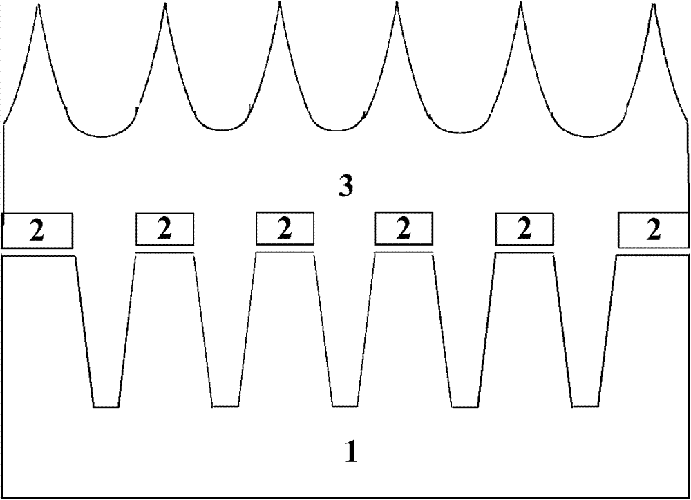
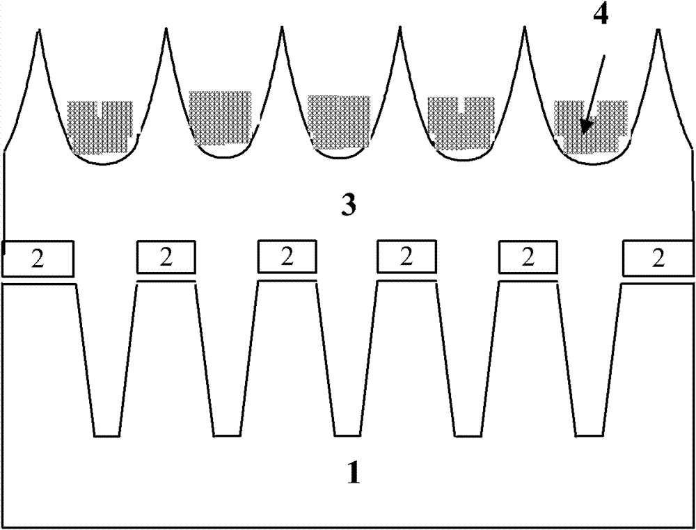
[0022] First refer to image 3 , forming a pad silicon oxide layer and a silicon nitride layer 2 on the substrate 1, photolithography / etching to form a high AR STI, and then using HDP-CVD to fill the high AR STI with silicon dioxide, the filled silicon dioxide and The pad oxide layer is bonded to form a silicon oxide isolation layer 3 . After the silicon oxide isolation layer 3 is deposited, the entire wafer is coated with photoresist; the reverse mask (that is, complementary to the exposure mask used to form STI) with shallow trench isolation is exposed, developed, Expose the silicon oxide in the protruding part of the non-shallow trench area, and retain the photoresist 4 in the concave part, such as image 3 Shown in the grid section.

[0023] Second, refer to Figure...

Embodiment 2

[0027] Figure 6 to Figure 7 A schematic cross-sectional view showing various steps of inclined ion implantation to increase silicon oxide removal rate according to Embodiment 2 of the present invention.

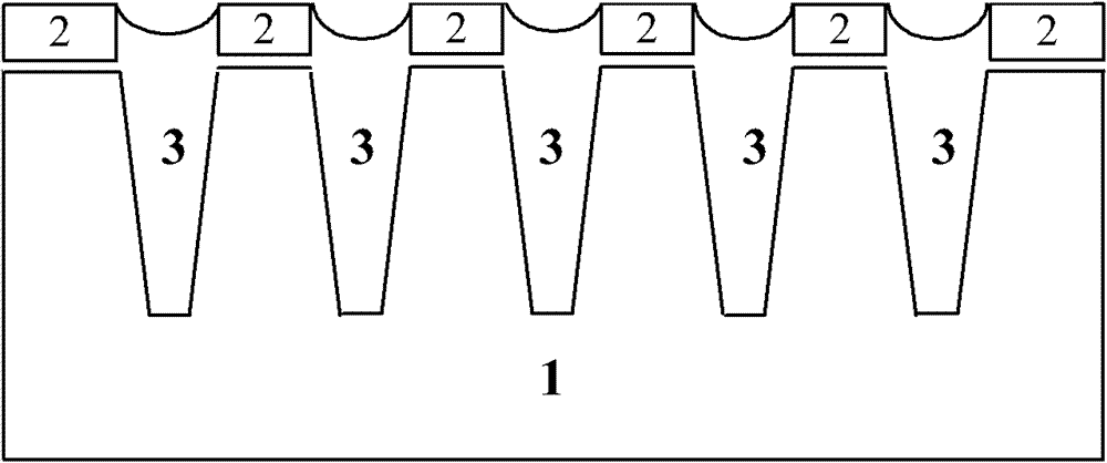
[0028] refer to Image 6, after the silicon oxide isolation layer 3 is deposited, the inclination angle of implantation is firstly determined according to the height H and spacing L of the pattern. In order to ensure that silicon oxide is not implanted in the recess during ion implantation, it is necessary to determine the implantation inclination angle θ, the expression of which is θ≈arctan(H / L), that is, the implantation inclination angle θ is approximately equal to arctan(H / L), where H and L can be obtained by layout design and measurement methods. Specifically, in the present invention, H is the difference in thickness of the silicon oxide layer, which is L is the width of the shallow trench STI, for example After determining the implantation inclination angle, per...


PUM


Abstract

The invention discloses a method for improving uniformity of shallow trench isolation (STI) chemical-mechanical planarization (CMP). The method comprising: performing deposition to form silicon oxide isolated layer in a shallow trench, the silicon oxide isolated layer having a projecting part and a sunken part; performing ion implantation to change crystalline state of the projecting part; performing chemico-mechanical polishing on the silicon oxide isolated layer until a stop layer is exposed. According to the method for improving uniformity of shallow trench isolation chemical-mechanical planarization, the ion implantation and a silicon oxide CMP process are combined. Through performing ion implantation on silicon oxide of the projecting part, the projecting part's silicon oxide material removing rate of CMP grinding liquid is increased. In a STI CMP process, a purpose of reducing oxide layer thickness gap of the shallow trench's isolation area and non-isolation area is achieved, the oxide layers being disposed on the shallow trench's isolation area and non-isolation area, thereby improving planarization and uniformity of the STI CMP process and reducing sunken and defective degree.

Description

technical field [0001] The invention relates to a method for manufacturing a semiconductor device, in particular to a method for improving the chemical mechanical planarization uniformity of shallow trench isolation. Background technique [0002] Since the introduction of shallow trench isolation (STI) technology from the 0.25um technology node, high-density isolation of devices has become possible. As technology nodes continue to shrink, in order to improve device density and isolation effects, the aspect ratio (AR) of the shallow trench itself increases accordingly. High-density plasma chemical vapor deposition (HDP-CVD) is the mainstream technique for filling shallow trenches. Through the cyclic process of deposition and etching, this technology overcomes the possible sealing problem at the top of the trench and completes the filling of the large AR trench structure. The effect after silicon oxide filling is shown in the appendix figure 1 . Among them, a pad oxide laye...

Claims


Application Information

Patent Timeline
Patent Type & Authority Applications(China)
IPC IPC(8): H01L21/3105H01L21/265
Inventor 杨涛刘金彪李俊峰赵超
Owner 江苏中科汉韵半导体有限公司
Why Eureka
Try Eureka