Defect and abrasion resistant surface coating and cutting tool

A cutting tool and surface coating technology, applied in the field of surface coating cutting tools, can solve the problems of decreased defect resistance, easy falling off, and increased surface roughness.

Inactive Publication Date: 2012-11-28
MITSUBISHI MATERIALS CORP
View PDF9 Cites 12 Cited by
  • Summary
  • Abstract
  • Description
  • Claims
  • Application Information

AI Technical Summary

Problems solved by technology

Spherical particles, or particles that are vertically elongated in the film thickness direction among slender particles, are easy to fall off due to resistance during cutting, and cause greater damage to the film surface when falling off, increasing the surface roughness so that Problems that lead to a decrease in chip resistance
Therefore, when only metal particles are simply d

Method used


Image

  • Defect and abrasion resistant surface coating and cutting tool
  • Defect and abrasion resistant surface coating and cutting tool
  • Defect and abrasion resistant surface coating and cutting tool

Examples


Embodiment 1

[0057] Prepare WC powder, TiC powder, ZrC powder, VC powder, TaC powder, NbC powder, Cr 3 C 2 Powder, TiN powder, TaN powder and Co powder are used as raw material powders. These raw material powders are combined into the compounding composition shown in Table 1. Further, wax is added and ball milled in acetone for 24 hours. After drying under reduced pressure, under a pressure of 98MPa, Press ISO·SEEN1203AFTN1 (hard matrix A~E) into a green compact with a specified shape, and vacuum sinter the green compact at a specified temperature in the range of 1370~1470°C for one hour in a vacuum of 5 Pa. After sintering, the cutting edge was chamfered and ground with a width of 0.15 mm and an angle of 20 degrees to manufacture tool substrates A to E made of WC-based cemented carbide, respectively.

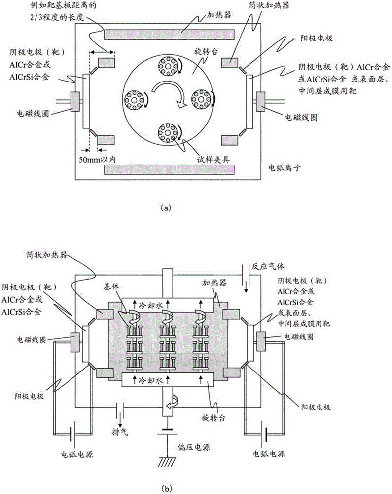
[0058] Next, load these tool bases A~E into the figure 1 In the arc ion plating apparatus shown, Ti bombardment was performed under the conditions shown in Table 2, and then, using the sa...


PUM

PropertyMeasurementUnit
Average layer thicknessaaaaaaaaaa

Abstract

The invention provides a defect and abrasion resistant surface coating and cutting tool. The surface of a body of the tool is coated with a hard coating layer via the physical evaporation. The hard coating layer is composed of a composite arbonitride layer or a nitride layer which is represented by the formula (Al1-x-y CrxSiy)(N1-zCz) and has the average thickness of 0.5 to 8.0[mu]m. The hard coating layer includes metal particles, and above 90 atom % of the elements of the metal particle are metal elements, and the cross section long diameter is from 0.05 to 1.0[mu]m. The metal particles are arranged in the hard coating layer at 3 to 20% of the longitudinal section area rate. In the metal particles, when the elements includes Al of above 50 atom%, and the aspect ratio of the longitudinal section is above 2.0, the cross long diameter form an 45 degree included angle with the surface of the substrate, the longitudinal section ratio is A%, and when the longitudinal section ratio is B%, 0.3<=A/(A+B).

Description

technical field [0001] The present invention relates to a surface coating that exhibits excellent wear resistance during long-term use by improving the chipping resistance of a hard coating layer, for example, in face milling of workpieces such as carbon steel and alloy tool steel. Covered cutting tools (hereinafter referred to as covered tools). Background technique [0002] Conventionally, in a surface-coated cutting tool as disclosed in Patent Document 1, for example, it is known that crystal grains of a compound in which crystals grow from droplets of a hard coating protrude from the surface of the coating. When the length in the longitudinal direction of the crystal grain is h (μm) and the film thickness of the hard film is T (μm), by setting 6≤T≤30 and 0.1≤h / T≤1.2, the droplet Large columnar crystals are grown as the starting point, and compressive stress is reduced to achieve a thicker film without compromising adhesion. [0003] In addition, as disclosed in Patent ...

Claims


Application Information

Patent Timeline
IPC IPC(8): B23C5/16
Inventor 佐藤峻仙北屋和明田中耕一田中裕介
Owner MITSUBISHI MATERIALS CORP
Why Eureka
Try Eureka