
Wind driven generator

A wind turbine and wind wheel technology, applied in wind turbine components, wind engines, wind power generation, etc., can solve the problems of unfavorable large-scale production, increase in engineering volume, transportation volume, and cost reduction, so as to save rent and The cost of road construction, the safety of working at heights, and the effect of reducing manufacturing costs

Inactive Publication Date: 2012-11-28
李泽宇
View PDF2 Cites 9 Cited by
  • Summary
  • Abstract
  • Description
  • Claims
  • Application Information

AI Technical Summary

Problems solved by technology

This kind of tower will undoubtedly increase the amount of engineering and transportation, and it cannot be disassembled, so the maintenance of the equipment on the top of the tower is also inconvenient.
In the past, all kinds of wind turbines were installed from the bottom of the tower, and then lifted and installed part by part with a very high crane. Almost all the installation work belongs to high-altitude operations, and parallel operations are prohibited during high-altitude operations. , so the installation period is very long, increasing the cost
Especially in the end, it is very difficult to hoist hundreds of tons of various equipment to a height of 100 meters with a giant crane. In order to drive the giant crane into the wind power site, the cost of road construction is also very high
Moreover, once it is installed, it is difficult to disassemble it, so it cannot be overhauled regularly, so that various equipment on the tower are required to have high reliability and long life
This requirement is extremely unfavorable to reduce costs, increase localization rate and mass production

Method used


Image

  • Wind driven generator
  • Wind driven generator
  • Wind driven generator

Examples


Embodiment Construction

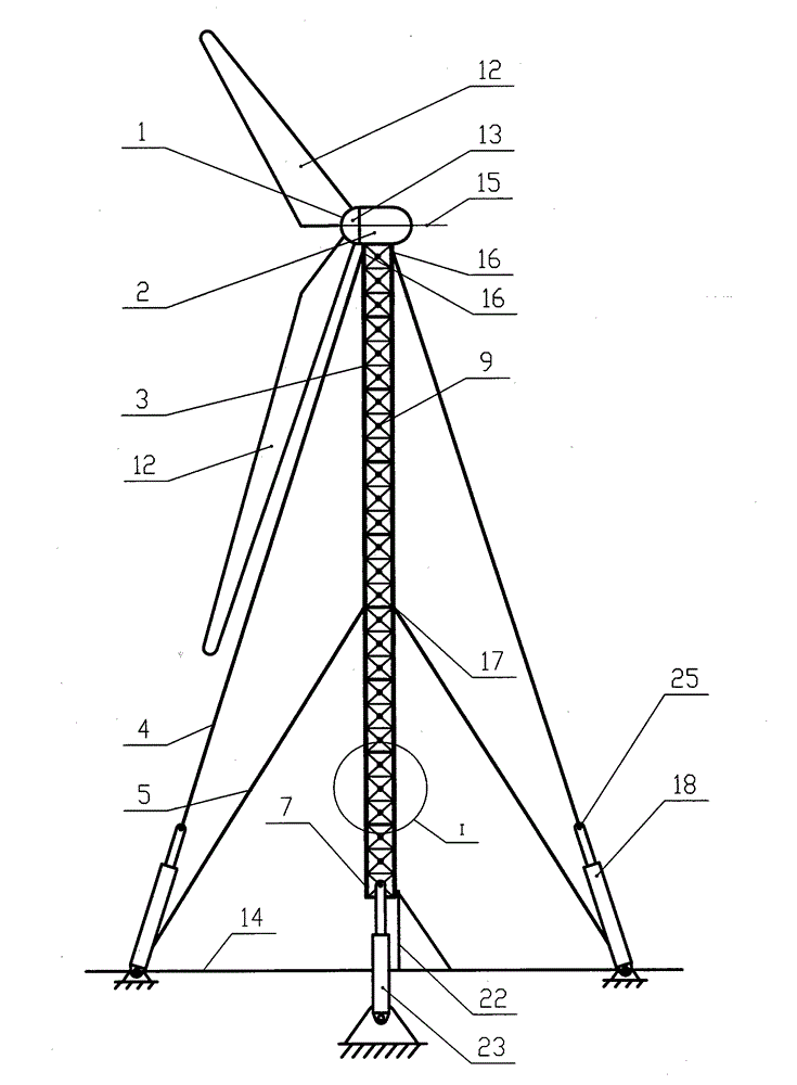
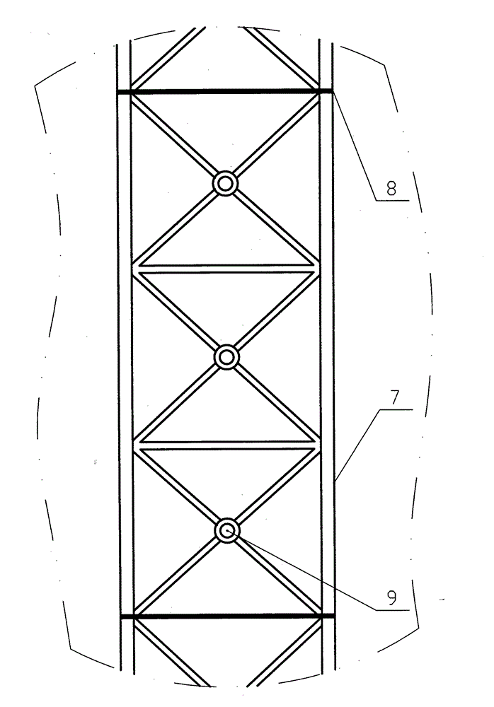
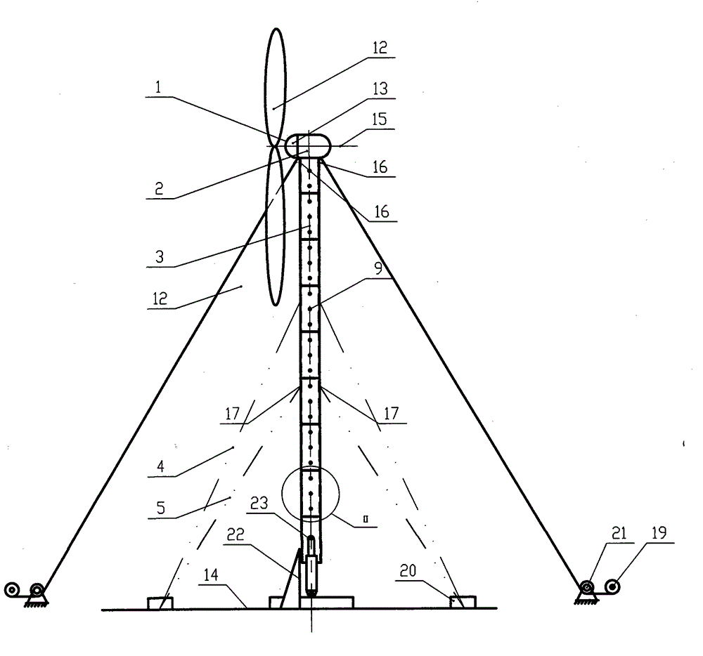
[0027] combine figure 1 and figure 2 , the first embodiment of a wind power generator in the present invention includes a wind rotor 1 formed by installing each blade 12 on a hub 13, and some types of wind rotors 1 are also equipped with a pitch control device. In the first embodiment, the blades 12 are inclined to the outside, and the blades 12 form an angle of 72° with the center line 15 of the horizontal axis; the tower 3 of the truss structure is disassembled into a tower subsection 7 that can be installed from the top first, and the tower The frame puppet 7 is connected to the adjacent tower puppet through the puppet end face 8; the engine room assembly part 2 including the power generation system and various auxiliary systems; Between the cable connector 16 and the foundation 14 figure 1 In the middle, the upper drag cable 4 is connected with the oil cylinder 18 to form the anti-fall device 25, which is the working state in the installation process; the lower drag cab...


PUM


Abstract

The invention discloses a horizontal shaft wind driven generator for wind driven generation, comprising a tower frame, a stay rope, an engine room assembly component and a wind wheel. The horizontal shaft wind driven generator is characterized in that the tower frame is divided into a structure which can be mounted from the top; the tower frame can be provided with a falling preventing device; under the protection of the falling preventing device, a mounted part can be lifted by a hydraulic cylinder for a certain height, and then, a tower frame part which is arranged below the mounted part and close to the mounted part can be mounted; and the dismounting process can be carried out in an inverted order. The tower frame of the wind driven generator is light in weight and convenient to transport, and can be mounted and dismounted rapidly by utilizing a hydraulic lift dismounting and mounting method; all equipment on the tower frame can be overhauled or replaced at regular intervals; the problem that the original wind driven generator has overhigh requirements for materials and service life is solved; and the import substitution rate can be favorably increased, and the cost can be favorably reduced.

Description

technical field [0001] The invention relates to a horizontal axis wind power generator for generating electricity with wind power. According to the output mode, wind power generators can be divided into grid-connected generators whose power can be integrated into the grid and decentralized wind power generators whose power can be used locally. A wind power generator of the present invention belongs to the above two wind power generators. According to the structure, wind power generators can be divided into horizontal axis wind power generators and vertical axis wind power generators. The present invention belongs to horizontal axis wind power generators. Background technique [0002] The horizontal axis wind turbine includes the assembly components of the nacelle composed of the transmission device, the power generation device, the yaw system, the main frame, and other auxiliary devices, and the tower supporting the nacelle up to tens of meters or even hundreds of meters. ...

Claims


Application Information

Patent Timeline
IPC IPC(8): F03D11/00F03D1/06
CPCY02E10/722Y02E10/721Y02E10/72
Inventor 李泽宇
Owner 李泽宇
Learn More