
Moving-coil loudspeaker with area-alterable capacitive vibration sensor

A dynamic speaker and vibration sensor technology, applied in the field of speakers, can solve problems such as unsatisfactory output linearity, complex phase relationship, too deep feedback, etc., achieve compact structure, reduce the lower limit of playback frequency, and have little external influence Effect

Active Publication Date: 2012-11-28
何永斌
View PDF5 Cites 11 Cited by
  • Summary
  • Abstract
  • Description
  • Claims
  • Application Information

AI Technical Summary

Problems solved by technology

[0006] (3) Transient distortion: The diaphragm is forced to vibrate under the action of the driving force of the voice coil. The vibration system has a certain mass and certain damping, and cannot quickly follow the rapidly changing input signal vibration, and there is always a certain delay. Time
This method has the following disadvantages: it takes a while for the sound signal to reach the pickup from the speaker, there is a long time lag in the feedback of the signal, and the phase relationship is complicated. Generally, the feedback cannot be added too deep, otherwise it will easily cause the system to oscillate.
It can be foreseen that this method is easily affected by the cone angle of the diaphragm as the reflective surface and the reflection characteristics of the diaphragm material. In its embodiment, ON2152 is used as the sensor. The specification of ON2152 lists the 90% reflection of white paper The Ic-D diagram reflected by the specular surface can prove that it is affected by the reflective surface, and its output linearity is not ideal

Method used


Image

  • Moving-coil loudspeaker with area-alterable capacitive vibration sensor
  • Moving-coil loudspeaker with area-alterable capacitive vibration sensor
  • Moving-coil loudspeaker with area-alterable capacitive vibration sensor

Examples


Embodiment 1

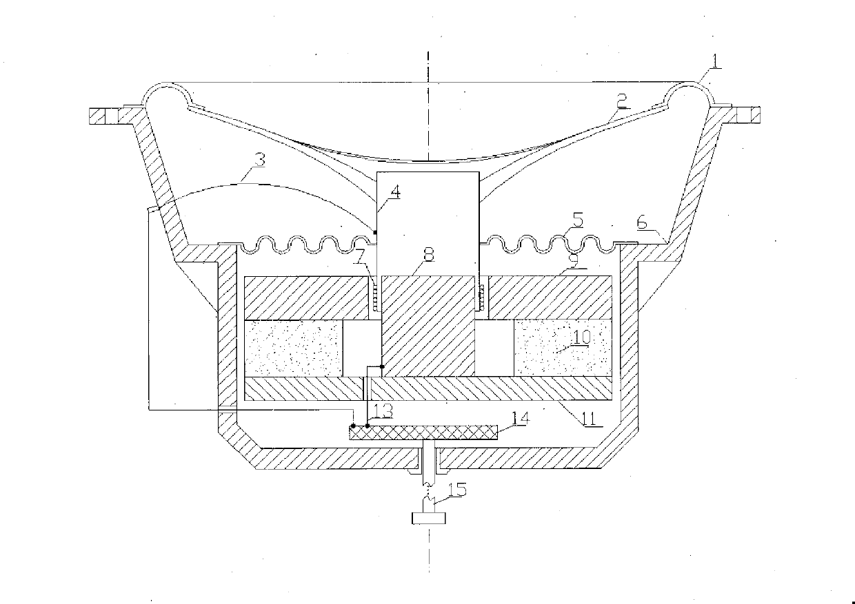
[0049] see figure 1 As shown, a dynamic speaker with a variable area capacitive vibration sensor is composed of a ring 1, a diaphragm 2, a centering piece 5, a basin frame 6, a conductive voice coil skeleton 4, a coil 7, and a magnetic column 8 , a magnetic upper plate 9, a permanent magnet 10, a magnetic lower plate 11, and a capacitance / motion signal conversion circuit 14. Between the magnetic column 8 and the magnetic upper plate 9, there is a . A variable-area capacitive vibration sensor 24 for measuring the displacement of the voice coil. The capacitance variable output by the variable-area capacitive vibration sensor 24 is input to the input terminal of the capacitance / motion signal conversion circuit 14 . The conductive voice coil bobbin 4 can be made of a metal sheet or an organic sheet coated with a conductive layer on the surface. This embodiment is a loudspeaker with an external magnetic circuit, the conductive voice coil bobbin 4 and the outer cylinder of the magn...

Embodiment 2

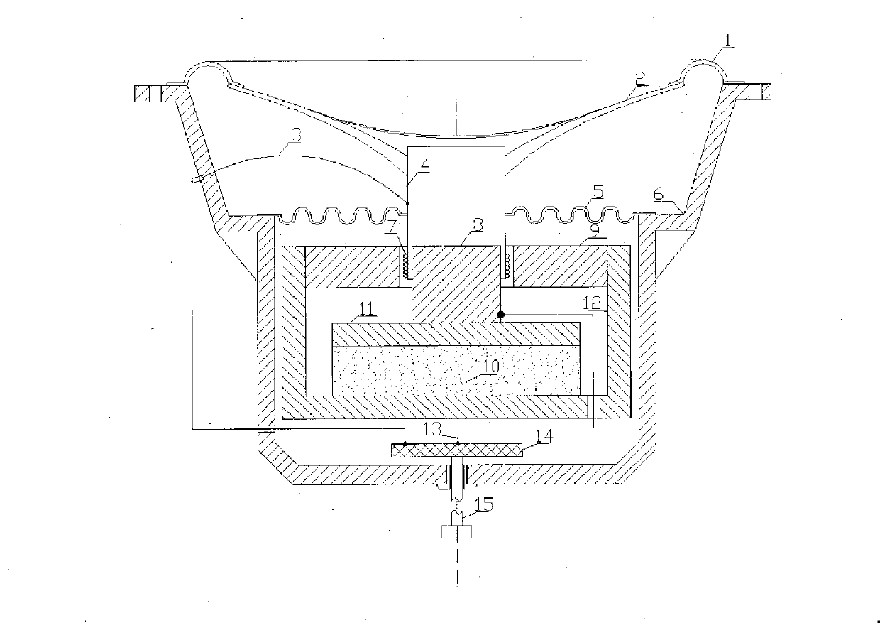
[0051] see figure 2 As shown, this embodiment is a loudspeaker with an internal magnetic axial magnetic circuit, and this kind of loudspeaker is provided with a magnetically conductive bowl 12 . Except that the structure of the magnetic circuit is different, the others are the same as the embodiment 1. During application, an insulating layer is generally inserted into one of the contact surfaces between the magnetically conductive column 8, the magnetically conductive lower plate 11, the permanent magnet 10, and the magnetically conductive bowl 12, and the magnetically conductive upper plate 9 and the magnetically conductive bowl 12 are grounded. , the highest signal-to-noise ratio can be obtained.

[0052] Some internal magnetic magnetic circuit speakers do not seem to have a magnetic upper plate 9. In fact, this design only expands the inner hole of the magnetic upper plate 9 to coincide with the outer diameter of the magnetic upper plate 9. At this time, the magnetic bowl...

Embodiment 3

[0056] see image 3 As shown, the present embodiment is a loudspeaker with an external magnetic magnetic circuit, and a straight cylindrical inner electrode 16 is fixedly installed on the outer surface of the magnetic conductive column 8, and the conductive voice coil bobbin 4 and the straight cylindrical inner electrode 16 constitute a variable area capacitive vibration sensor 24 , the conductive voice coil bobbin 4 and the straight cylindrical inner electrode 16 are respectively connected to the input terminal of the capacitance / motion signal conversion circuit 14 through the first conductive lead 3 and the second conductive lead 13 . In order to obtain a sufficiently large linear output amplitude, the axial length of the straight cylindrical inner electrode 16 should be such that the voice coil does not exceed the upper and lower edges of the straight cylindrical inner electrode 16 when the voice coil moves with the maximum amplitude. In order to prevent the thickness of th...


PUM


Abstract

The invention provides a moving-coil loudspeaker with an area-alterable capacitive vibration sensor, of which the magnetic path structure is an outer magnetic path or an inner magnetic path. A coil is wound on a conductive voice coil framework to form a voice coil, a capacitive / moving signal converting circuit is provided, the area-alterable capacitive vibration sensor positioned in the same axial direction as the conductive voice coil framework and used for measuring the displacement of the voice coil is arranged between a magnetic-conductive column and a magnetic-conductive upper plate, and capacitance variable output by the area-alterable capacitive vibration sensor is transmitted to the input terminal of the capacitive / moving signal converting circuit. As the capacitance value of the area-alterable capacitive vibration sensor and the displacement of the voice coil form a linear relationship, wide-range linear output is achieved, and the measurement requirement of a large-amplitude highly-dynamic low-frequency loudspeaker is particularly satisfied; and a moving signal of the loudspeaker voice coil can be obtained through detecting the output of the sensor by the capacitive / moving signal converting circuit to serve as a feedback signal to be input into the feedback input terminal of a moving servo amplifier, so that the closed-loop control of the loudspeaker is realized.

Description

technical field [0001] The invention relates to the technical field of loudspeakers, in particular to a dynamic-coil loudspeaker with a variable-area capacitive vibration sensor. Background technique [0002] The distortion degree of digital audio source and power amplifier in the playback link of the electro-acoustic field can easily reach below 0.01%. However, the distortion of the speaker at the end of the sound reproduction link is generally greater than 1%, and the ultra-low frequency range reaches more than 5%, which becomes the bottleneck for further improvement of the fidelity of the sound reproduction system. [0003] According to the structure of the magnetic circuit, the dynamic speaker can be divided into two types: internal magnetic type and external magnetic type, and the internal magnetic type can be divided into axial magnetic circuit and radial magnetic circuit according to the magnetization direction of the magnet. The length relationship between coil and ...

Claims


Application Information

Patent Timeline
IPC IPC(8): H04R9/06H04R9/02
Inventor 何永斌
Owner 何永斌
Learn More