Plastic grinder

A pulverizer and plastic technology, which is applied in the direction of plastic recycling, mechanical material recycling, recycling technology, etc., can solve the problems of large pieces, complex structure, and easy blockage of machines by crushed objects

Active Publication Date: 2012-12-12
NINGBO HUARE MACHINERY MFG
View PDF6 Cites 4 Cited by
  • Summary
  • Abstract
  • Description
  • Claims
  • Application Information

AI Technical Summary

Problems solved by technology

However, this type of equipment generally has a complex structure and low production efficiency. Generally, it can only crush small-volume plastic products, and the crushing effect is not ideal, especially for large-caliber hollow barrel plastic products. Low, the product will bounce up, so there will be large pieces of debris, the crushing is not thorough, these large pieces of crushed objects are easy to block the machine and reduce the service life of the pulverizer

Method used


Image

  • Plastic grinder
  • Plastic grinder
  • Plastic grinder

Examples


Embodiment 1

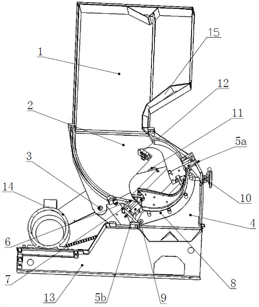
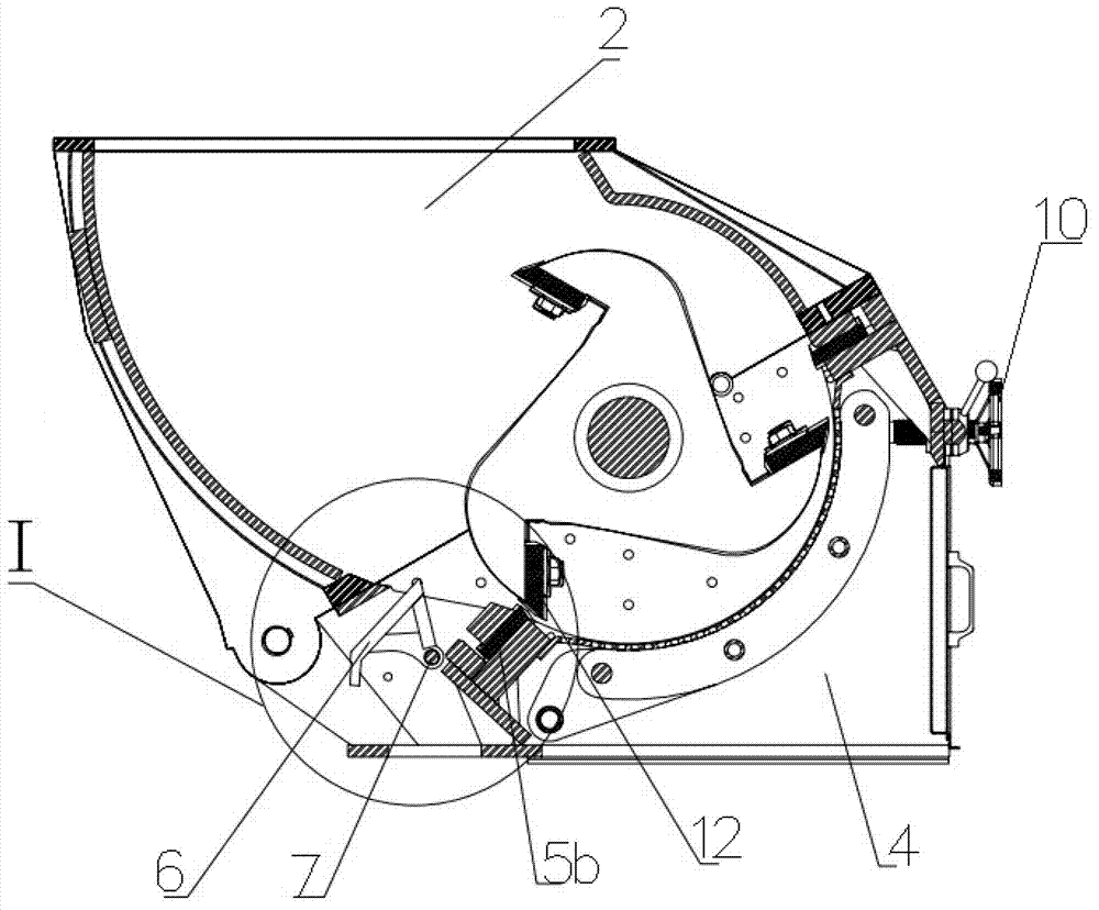
[0021] Such as Figure 1-7 As shown, a plastic pulverizer includes a feed hopper 1, an upper body 2 of the crushing chamber, a rotating shaft 3, a lower body 4 of the crushing chamber, a front fixed knife 5a, a rear fixed knife 5b, an insert 6 in the lower body, and a rotating shaft 7 for the inner insert , screen device 8, screen frame shaft 9, locking rod 10, main shaft rotor 11, rotating knife 12, chassis 13, power transmission device 14, folding plate 15;

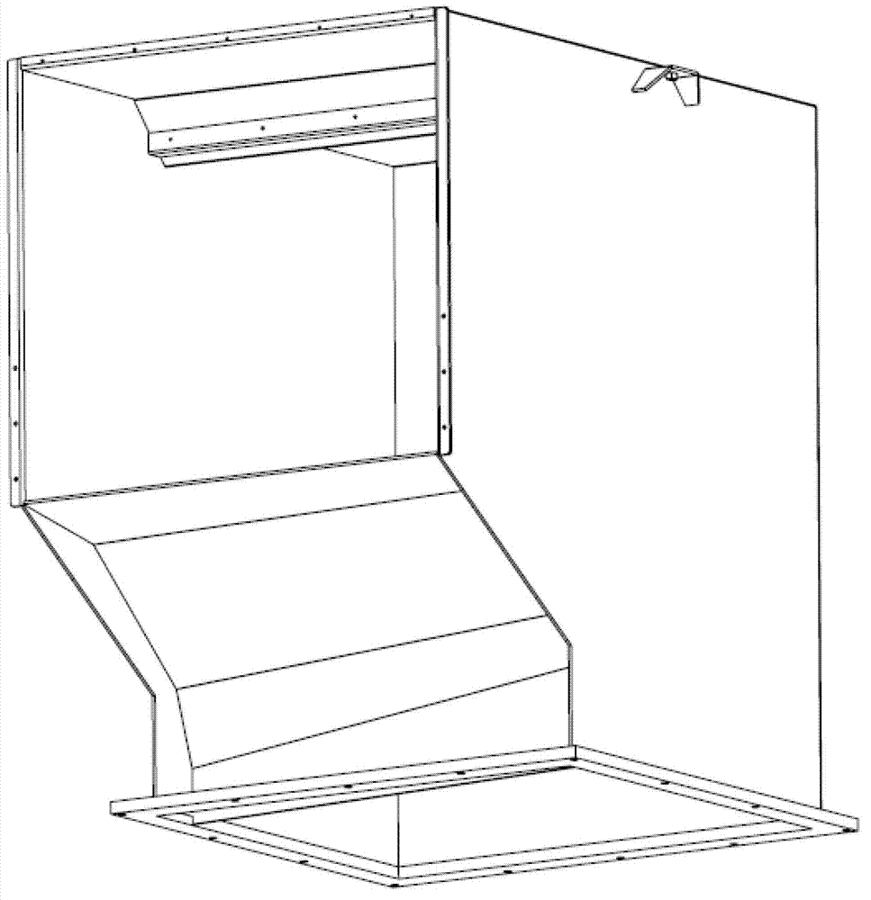
[0022] The lower part of the front side of the feed hopper 1 is concave inward to form a continuous folded plate 15, and the feed hopper 1 is fixedly installed on the upper body 2 of the crushing chamber. The front and rear sides of the upper body 2 of the crushing chamber are curved plates or approximate arcs. type folded plate;

[0023] The front end of the upper body 2 of the crushing chamber is locked and the rear end is pinned to the lower body 4 of the crushing chamber through the rotating shaft 3. The lower body...

Embodiment 2

[0034] The whole crushing process is as follows: plastic parts enter the feed hopper 1 from the entrance, and fall on the folding plate 15 in turn. Since the folding plate 15 is connected by several inclined surfaces at a certain angle to form a continuous transition surface, the plastic parts, especially the barrel-shaped plastic When it falls from the feed hopper 1 and rolls down along the folding plate 15, it will automatically turn horizontally; at this time, the power transmission device 14 drives the main shaft rotor 11 to rotate, and several groups of rotating knives 12 on the main shaft rotor 11 also rotate accordingly, and It forms a shearing movement with the front fixed knife 5a and the rear fixed knife 5b at the lower part of the front and rear arc-shaped plates of the upper body 2 of the crushing chamber; because the insert 6 in the lower body expands the space of the crushing storage area, the plastic parts are placed on the crushing chamber. The stress point of t...


PUM


Abstract

The invention relates to a plastic grinder which comprises a feeding hopper installed on a grinding chamber upper body. The front end of the grinding chamber upper body is locked, and the back end of the grinding chamber upper body is in pin connection with a grinding chamber lower body through a rotating shaft. A front fixed cutter and a back fixed cutter are respectively installed at the cutter installation positions in front of and at the back of the grinding chamber lower body. A lower body inside insert is installed at the extending position on the lower portion of a back arc plate of the grinding chamber upper body, the lower body inside insert is in pin connection with the grinding chamber lower body through the rotating shaft and is locked, and a screen device is in pin connection with the grinding chamber lower body through a screen frame rotating shaft and is lifted in spiral mode through a locking rod to be bonded with the lower portion on the front installation cutter face of the grinding chamber lower body. A spindle rotor is installed in the middle of the grinding chamber lower body in suspension mode, a rotating movable cutter is installed on the spindle rotor, the grinding chamber lower body is fixed on a base frame, and a power transmission device is connected with the spindle rotor and can drive the spindle rotor to rotate. By means of the lower body inside insert, the plastic grinder can effectively expand grinding material storing area space, improves cutting material grabbing points, improves grinding efficiency and can grind large-diameter grinding products.

Description

technical field [0001] The invention belongs to the technical field of pulverizing devices, in particular to a plastic pulverizer. Background technique [0002] With the application of plastic products more and more widely, a large amount of waste plastic products have also been produced. How to recycle has gradually become a topic of social concern. The knife rotates or the rotating blade crushes it into a suitable particle size before processing. [0003] Existing plastic pulverizers can pulverize various plastics such as plastic profiles, pipes, rods, silk threads, films, and waste rubber products. However, this type of equipment generally has a complex structure and low production efficiency. Generally, it can only crush small-volume plastic products, and the crushing effect is not ideal, especially for large-caliber hollow barrel plastic products. If the product is low, the product will bounce, so that there will be large pieces of debris, and the crushing is not comp...

Claims


Application Information

Patent Timeline
Patent Type & Authority Applications(China)
IPC IPC(8): B02C18/14B02C18/18B29B17/04
CPCY02W30/52Y02W30/62
Inventor 徐小军叶慎熙
Owner NINGBO HUARE MACHINERY MFG
Why Eureka
Try Eureka