Supercharge Your Innovation With Domain-Expert AI Agents!

Retainer for tapered roller bearing and bearing with retainer

A tapered roller bearing and bearing cage technology, applied in the direction of roller bearings, bearing components, shafts and bearings, can solve problems such as raceway contact and bearing failure, and achieve increased clearance, increased strength, and increased flexibility. and longevity effects

Active Publication Date: 2012-12-12
中浙高铁轴承有限公司
View PDF5 Cites 0 Cited by
  • Summary
  • Abstract
  • Description
  • Claims
  • Application Information

AI Technical Summary

Problems solved by technology

The outer edge surface of the large end ring of the cage of the present invention is a tapered surface, because the gap between the outer diameter of the cage and the raceway of the inner peripheral surface of the bearing outer ring is small, and because the gap between the pocket hole and the tapered roller There is a radial clearance between the bearings. During the operation of the bearing, especially when the bearing speed changes, the cage is subjected to centrifugal force, and the raceway contact between the outer diameter of the cage and the inner peripheral surface of the outer ring may occur. , which will cause the bearing to fail

Method used


Image

  • Retainer for tapered roller bearing and bearing with retainer
  • Retainer for tapered roller bearing and bearing with retainer
  • Retainer for tapered roller bearing and bearing with retainer

Examples


Embodiment Construction

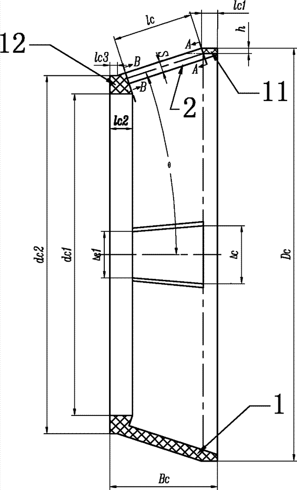
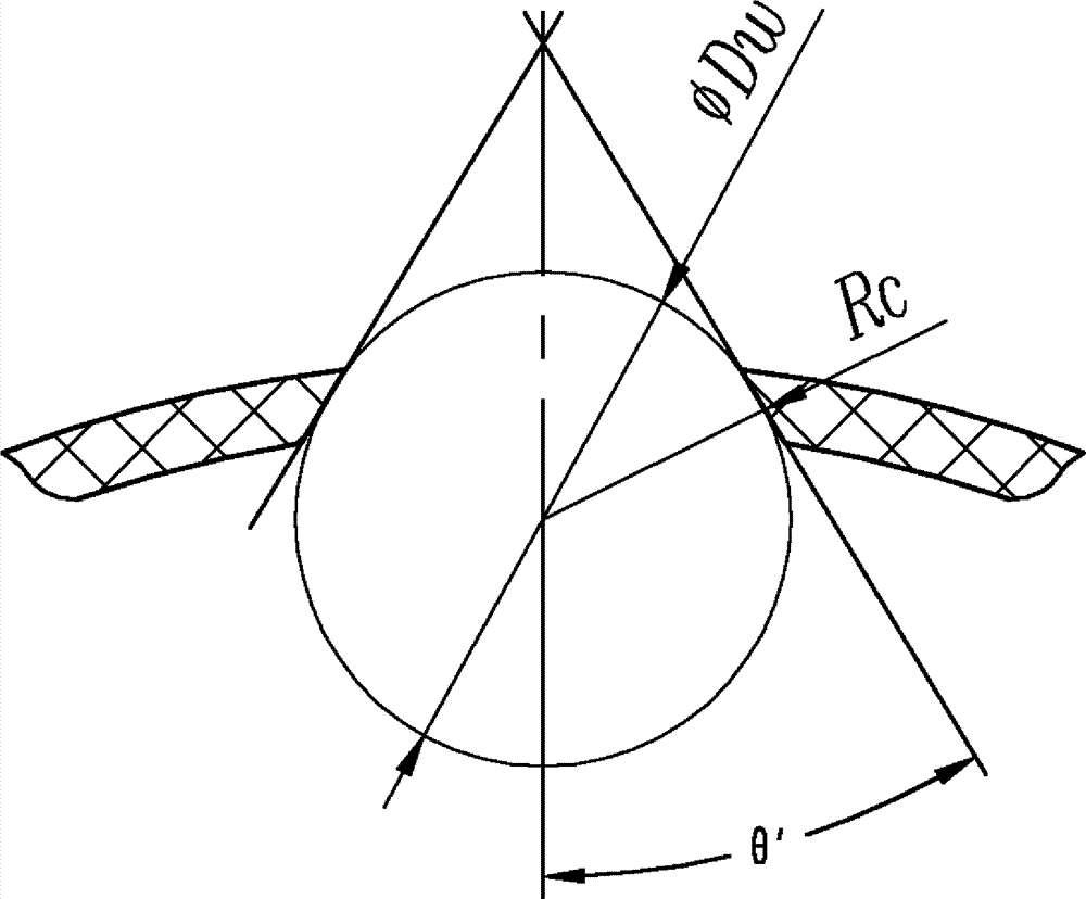
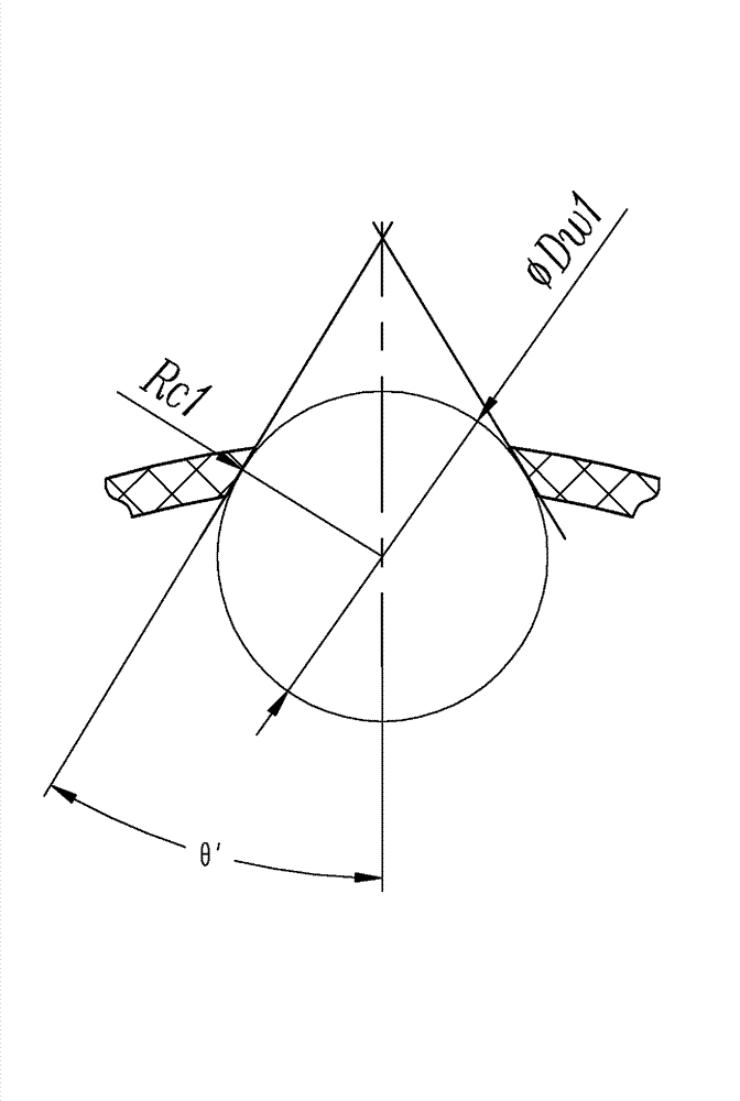
[0021] An embodiment of a cage for a tapered roller bearing, taking the structure of the 32010 / HV bearing cage as an example (unit: mm): the diameter of the center circle of the large and small heads of the tapered rollers fD w , fD w1 The values ​​are 6.89 and 6.18, and the cage structure is as follows Figure 1-3 As shown, it includes a frame body 1 made of polyetheretherketone composite material. The frame body includes a large end ring 11 and a small end ring 12 arranged side by side in the axial direction. The outer peripheral surface of the large end ring 11 is in line with the bearing The cylindrical surface parallel to the axis of the cage, the outer diameter of the big end ring D C =4.2, the radial thickness of the big end ring 11 h=1.30, the axial width L of the big end ring C1 =2, the outer peripheral surface of the small end ring 12 has a cylindrical surface parallel to the axis of the bearing cage from its front end to the rear end, the front end surface of the ...


PUM

PropertyMeasurementUnit
Axial lengthaaaaaaaaaa

Abstract

The invention discloses a retainer for a tapered roller bearing and a bearing with the retainer. The retainer for the tapered roller bearing comprises a retainer body, the retainer body comprises a large end ring and a small end ring which are parallelly arranged in the axial direction, transverse ribs which are circumferentially distributed are connected between the large end ring and the small end ring, the two adjacent transverse ribs, the large end ring and the small end ring define a tapered pocket which is used for placing the tapered rollers, the walls at the large end and the small end of the tapered pocket are provided with parallel slopes, the outer sides of the slopes are close to the small end, the inner sides of the slopes are close to the large end, stopping surfaces which are used for preventing the tapered rollers from coming off are arranged on the opposite surfaces of the two adjacent transverse ribs, and the outer circumferential surface of the large end ring is a cylindrical surface with the axis of the bearing retainer as a centre line. According to the retainer for the tapered roller bearing and the bearing with the retainer, the outer circumferential surface of the large end ring is designed to be the cylindrical surface so that the gap between the outer diameter of the retainer and an inner roller way of an outer ring is enlarged, the bearing is effectively prevented from contacting with the inner roller way of the outer ring, the rotating flexibility of the bearing is improved, and the service life of the bearing is prolonged.

Description

technical field [0001] The invention belongs to the technical field of bearings, in particular to a cage for tapered roller bearings, and simultaneously the invention also relates to a bearing using the cage. Background technique [0002] At present, the cage for tapered roller bearings such as the Chinese patent announcement number is CN202040212U, the announcement date is November 16, 2011, and the title is "a tapered roller cage". A tapered roller cage is disclosed in the specification. It includes a frame body, the frame body includes a large end ring and a small end ring arranged side by side in the axial direction, horizontal ribs distributed along the circumferential direction are connected between the large and small end rings, and the outer peripheral surfaces of the large and small end rings are in contact with the The outer surfaces of the transverse ribs are on the same conical surface. Two adjacent transverse ribs and the large and small end rings form a tapered...

Claims


Application Information

Patent Timeline
IPC IPC(8): F16C33/46F16C19/36
Inventor 李亮焦育洁
Owner 中浙高铁轴承有限公司
Features
  • R&D
  • Intellectual Property
  • Life Sciences
  • Materials
  • Tech Scout
  • Unparalleled Data Quality
  • Higher Quality Content
  • 60% Fewer Hallucinations
Learn More