Non-contact ultrasonic testing method

A detection method, non-contact technology, applied in the direction of measuring devices, geophysical measurement, instruments, etc., can solve the problems that the signal cannot reach the deep layer of the model, the ultrasonic emission energy is not enough, and the excitation effect is affected, so as to solve the problem of the detection and emission devices on the model. The influence of the simulation effect, the simulation effect is realistic, and the effect of increasing the acquisition speed

Active Publication Date: 2012-12-12
CHINA PETROLEUM & CHEM CORP +1
View PDF5 Cites 16 Cited by
  • Summary
  • Abstract
  • Description
  • Claims
  • Application Information

AI Technical Summary

Problems solved by technology

[0011] Existing ultrasonic detection methods have certain shortcomings and limitations when used for geological model detection
[0012] ① Piezoelectric ultrasonic probes are relatively simple and low in price, but when performing geological model testing, there will be some problems when using piezoelectric probes for transmission and reception
The damage of this point will affect the next excitation effect at this point
When performing physical model detection, it is required to emit ultrasonic signals multiple times at the same emission point (we call it the shot point), which means that the point is irradiated by the intense pulsed laser source multiple times, and each irradiation is required The state of the previous point will not change, that is, the repeatability is good, but it is difficult to achieve this with an intense pulsed laser source
If the emission energy is reduced, the generated ultrasonic emission energy is not enough, and the signal cannot reach the deep layer of the model

Method used


Image

  • Non-contact ultrasonic testing method
  • Non-contact ultrasonic testing method
  • Non-contact ultrasonic testing method

Examples


Embodiment Construction

[0042] Below in conjunction with accompanying drawing, the present invention is described in further detail:

[0043] A non-contact ultrasonic detection method, the method uses high-voltage pulse or alternating voltage to excite the high-frequency vibration of the non-contact focused probe, and then induces the transmission of sound waves, and focuses the radiated energy of the sound waves, and then the focused The sound wave is emitted to the shot point of the geological model to be tested, and the ultrasonic wave is generated at the shot point and transmitted to the inside of the geological model to be tested. At the same time, the detection point of the geological model to be tested is detected to obtain a voltage signal, and then the voltage signal It is converted into a digital signal and transmitted to a computer for processing.

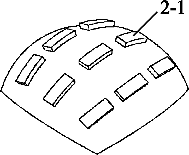
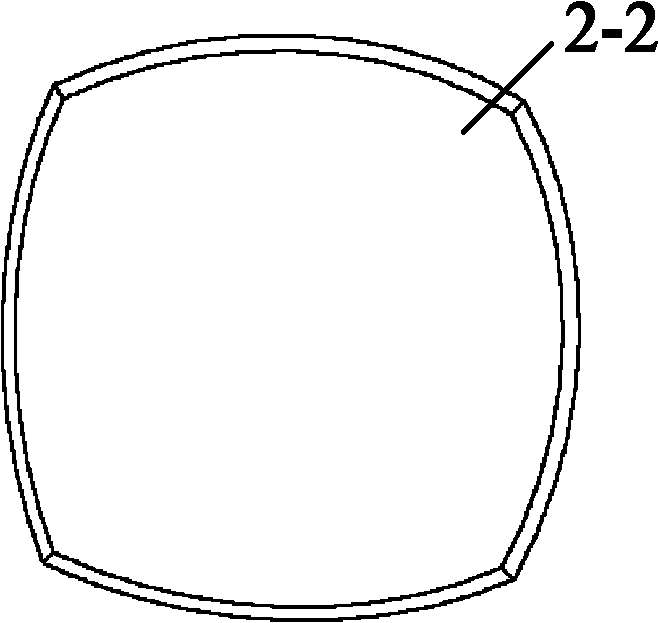
[0044] The non-contact focusing probe used in the method is designed as shown in Figure 2. What Figure 2 provides is the overall view of the n...


PUM


Abstract

The invention provides a non-contact ultrasonic testing method and belongs to the field of ultrasonic vibration testing. The method is characterized in that high-voltage pulses or alternating voltage is adopted to excite high-frequency vibration of a non-contact focusing probeand further to induce sound waves to be transmitted out, sound wave radiation energy is focused, focused sound waves are emitted to a shot point of a tested geologic model, ultrasonic waves are generated on the shot point and transmitted to the interior of the tested geologic model, simultaneously a detection point of the tested geologic model is detected to obtain voltage signals, and the voltage signals are converted to digital signals and transmitted to a computer to be processed. The non-contact ultrasonic testing method solves the problem of various normal geologic model simulation methods, can perform large-scale multipoint non-contact ultrasonic detection for complex surface models and meets special requirements of modern geophysical prospecting fine simulation.

Description

technical field [0001] The invention belongs to the field of ultrasonic vibration detection, and in particular relates to a non-contact ultrasonic detection method, which realizes vibration detection by generating and receiving ultrasonic signals in a non-contact manner under indoor conditions. Background technique [0002] Earthquake physical simulation research refers to the use of physical models to study earthquakes and related phenomena (especially fluctuation phenomena). It is an important part of experimental geology, also known as model geology. The most commonly used method in model geology studies is the ultrasonic method, and is therefore often referred to as ultrasonic seismic modeling. Ultrasonic seismic physical model experiments conduct indoor simulation observations of the propagation of seismic waves in various complex geological bodies through the observation of ultrasonic propagation in geological models, and conduct seismological research based on the obs...

Claims


Application Information

Patent Timeline
Patent Type & Authority Applications(China)
IPC IPC(8): G01V1/00G01V1/28
Inventor 宗遐龄陈超马中高黄德娟王辉明
Owner CHINA PETROLEUM & CHEM CORP
Why Eureka
Try Eureka