Amorphous, microcrystal or nanocrystalline alloy stator core and method for producing same

A nanocrystalline alloy and stator core technology, applied in the microcrystalline or nanocrystalline alloy stator core and its manufacturing, high-performance amorphous field, can solve the problems of large cutting thickness, low efficiency, and large axial height of the stator core.

Active Publication Date: 2012-12-12
JIANGSU JICUI ANTAI CHUANGMING ADVANCED ENERGY MATERIALS RES INST CO LTD
View PDF3 Cites 24 Cited by
  • Summary
  • Abstract
  • Description
  • Claims
  • Application Information

AI Technical Summary

Problems solved by technology

However, the axial height of the stator core is generally large, and it is difficult to achieve such a large cutting thickness by high-efficiency laser cutting, plasma cutting and water jet cutting. Generally, only the low-efficiency EDM method can be used for cutting

Method used


Image

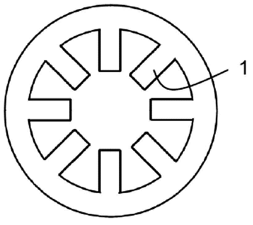
  • Amorphous, microcrystal or nanocrystalline alloy stator core and method for producing same
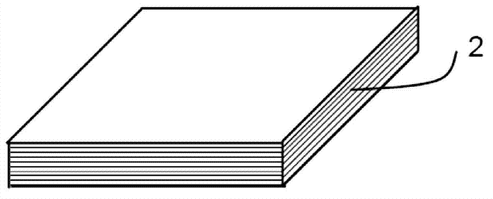
  • Amorphous, microcrystal or nanocrystalline alloy stator core and method for producing same
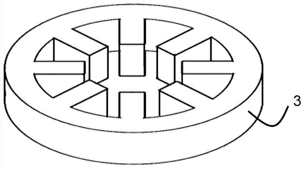
  • Amorphous, microcrystal or nanocrystalline alloy stator core and method for producing same

Examples


Embodiment 1

[0043] The composition of the strip for making the amorphous alloy stator core is Fe 80 Si 9 B 11 (at.%), the strip thickness is 30±1μm, the width is 142mm, and the surface is smooth and smooth. First, the amorphous strip was cut into square amorphous alloy flakes with a length of 142 mm using a cross-cutting device, and then these square amorphous alloy flakes were subjected to magnetic field annealing treatment under nitrogen protection. The described magnetic field annealing process conditions are as follows:

[0044] 1) Fill the electric furnace with nitrogen as a protective gas; 2) When the temperature rises to 250°C at a heating rate of 20°C / min, a DC magnetic field with a strength of 100mT is applied, and the direction of the magnetic field is perpendicular to the direction of the cast strip of the amorphous alloy strip. Hold at 250°C for 120min, and then heat up to 390°C at the same heating rate; 3) Keep the direction and intensity of the magnetic field unchanged, a...

Embodiment 2

[0053] The composition of the strip for making the amorphous alloy stator core is Fe 80 Si 9 B 11 (at.%), the strip thickness is 30±1μm, the width is 142mm, and the surface is smooth and smooth. First, the amorphous strip was cut into square amorphous alloy flakes with a length of 142 mm using a transverse shearing machine, and then these square amorphous alloy flakes were subjected to magnetic field annealing treatment under nitrogen protection. The magnetic field annealing treatment process is as follows:

[0054] 1) Fill the electric furnace with nitrogen as protective gas; 2) When the temperature rises to 280°C at a heating rate of 20°C / min, a DC magnetic field with a strength of 100mT is intensified, and the direction of the magnetic field is perpendicular to the direction of the cast strip of the amorphous alloy strip. Heat up to 390°C at the same heating rate; 3) Keep the direction and intensity of the magnetic field unchanged, and keep at 390°C for 120 minutes; 4) S...


PUM

PropertyMeasurementUnit
thicknessaaaaaaaaaa
thicknessaaaaaaaaaa
thicknessaaaaaaaaaa

Abstract

The invention provides an amorphous, microcrystal or nanocrystalline alloy stator core and a method for producing the same. The method for producing the stator core comprises the following steps that an amorphous, microcrystal or nanocrystalline alloy strip is laterally cut into a plurality of rectangular sheets with the same shape and size; the alloy sheets which are obtained through lateral cutting are subjected to annealing treatment; a plurality of alloy sheets which are obtained through annealing treatment are subjected to resin solidification treatment to obtain amorphous, microcrystal or nanocrystalline alloy sheets with the preset thickness; any one mode of laser cutting, plasma cutting, water cutting, wire cut electrical discharge machining, flame cutting and chemical etching is used to cut the alloy sheets with the preset thickness to obtain annular amorphous, microcrystal or nanocrystalline alloy splicing modules or at least one single-tooth circular arc splicing module; and the annular amorphous, microcrystal or nanocrystalline alloy splicing modules or at least one single-tooth circular arc splicing module are laminated or spliced to form the stator core. According to the method for producing the stator core, the production efficiency can be increased, and the cost can be lowered.

Description

technical field [0001] The present application relates to a method for manufacturing a magnetic circuit component of a motor, and more particularly, to a high-performance amorphous, microcrystalline or nanocrystalline alloy stator core for a high-frequency motor and a method for manufacturing the same. Background technique [0002] In recent years, many application fields have put forward higher requirements for the performance of motors, such as aerospace, electric vehicles, high-speed machine tool processing, high-speed flywheel energy storage, high-speed compressors, high-speed centrifuges, etc., which not only require the motor to have high efficiency, but also Motors are also required to have high power density, high torque density or high rotational speed. In order to achieve high speed, high power density or high torque density of the motor, it is often necessary to design the electromagnetic frequency of the motor at 400~1500Hz or even higher. [0003] The iron loss...

Claims


Application Information

Patent Timeline
Patent Type & Authority Applications(China)
IPC IPC(8): H02K15/02B82Y40/00
Inventor 周少雄张广强王立军李山红
Owner JIANGSU JICUI ANTAI CHUANGMING ADVANCED ENERGY MATERIALS RES INST CO LTD
Why Eureka
Try Eureka