Micro-crack flat heat pipe and manufacturing method thereof

A technology of a flat heat pipe and a manufacturing method, applied in the field of electronics, can solve the problem of insufficient heat dissipation capability of the heat pipe, and achieve the effects of simple and easy technical means, improved heat transfer, and low backflow resistance.

Active Publication Date: 2012-12-19
SOUTH CHINA UNIV OF TECH
View PDF4 Cites 13 Cited by
  • Summary
  • Abstract
  • Description
  • Claims
  • Application Information

AI Technical Summary

Problems solved by technology

[0004] The purpose of the present invention is to overcome the shortcomings and deficiencies of the prior art, provide a micro-crack flat heat pipe with simple structure and convenient processing and its manufacturing method, and solve the problem of insufficient heat dissipation capacity of the existing heat pipe

Method used


Image

  • Micro-crack flat heat pipe and manufacturing method thereof
  • Micro-crack flat heat pipe and manufacturing method thereof
  • Micro-crack flat heat pipe and manufacturing method thereof

Examples


Embodiment 1

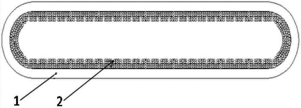
[0029] Such as Figure 1~4 shown. The micro-crack flat heat pipe of the present invention comprises a pipe body 1 and a porous capillary layer 2 attached to the inner wall of the pipe body 1; the surface of the porous capillary layer 2 has a plurality of grooves, which are evenly distributed along the circumference of the inner wall of the pipe body 1; The tube body 1 adopts a metal flat heat pipe, and the tube body 1 is filled with deionized distilled water or ethanol.

[0030] The manufacturing method of the micro-crack flat heat pipe of the present invention can be realized through the following steps:

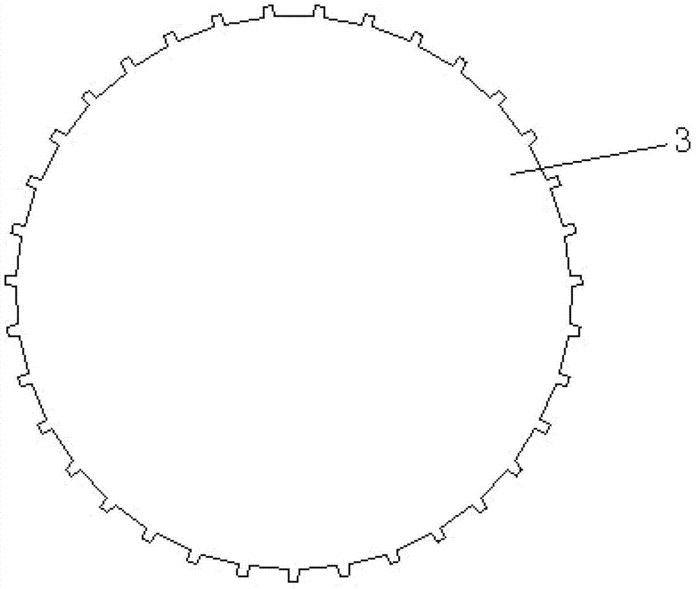
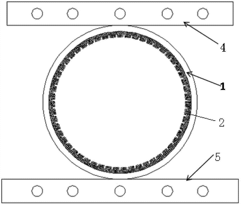
[0031] (1) Prepare a tube body 1 (circular metal heat pipe) and a sintered mandrel 3, the diameter of the sintered mandrel is smaller than the inner diameter of the tube body 1, place the sintered mandrel in the middle of the tube body 1, and the tube body There is a gap between 1 and the sintered mandrel 3; one end of the tube body 1 is retracted, and then the tube body ...

Embodiment 2

[0040] This embodiment is the same as Embodiment 1 except for the following features.

[0041] Such as Figure 5 ~ Figure 7 shown. In the above step (1), grooves are opened on the inner surface of the pipe body 1 , and the surface of the sintered mandrel is a smooth surface (not shown in the figure).


PUM


Abstract

The invention discloses a micro-crack flat heat pipe and a manufacturing method thereof. The micro-crack flat heat pipe comprises a pipe body and a porous capillary layer attached to an inner wall of the pipe body, wherein a plurality of slots are arranged on the surface of the porous capillary layer and are uniformly distributed along the circumference of the inner wall of the pipe body. The manufacturing method comprises the following steps: placing a sintered core bar on the middle part in the pipe body and arranging a clearance between the pipe body and the sintered core bar; contracting the tail at one end of the pipe body and then performing de-rusting and de-oiling treatment on the pipe body and the sintered core bar; filling metal powder into the clearance between the pipe body and the sintered core bar and placing the metal powder together with the pipe body into a high-temperature sintering furnace for sintering; after sintering, taking out the pipe body, cooling to room temperature and then taking out the sintered core bar; vacuumizing, filling a working medium and sealing at the other end of the pipe body; and flattening and shaping the pipe body. A phase-change flattening technology is adopted by the invention; a continuous and big enough porous capillary layer, namely, a micro-crack channel space, is obtained according to a sintered core bar inducing method; a steam channel is supplied; and the heat transfer and mass transfer properties of the flat heat pipe are obviously increased.

Description

technical field [0001] The invention relates to heat dissipation components in the electronic field, in particular to a micro-crack flat heat pipe and a manufacturing method thereof. Background technique [0002] With the rapid development of high-performance electronic chip technology and the continuous improvement of electronic packaging and integration, the heat flux density of the chip will increase sharply and the effective heat dissipation space will become increasingly narrow. The traditional heat dissipation methods can no longer meet the heat dissipation requirements. The cooling system is developed and optimized. Because the flat heat pipe has the characteristics of fast heat transfer and small space occupation, it is widely used in electronic products in these small spaces. [0003] Traditional micro heat pipes with liquid-absorbent cores mainly include grooved heat pipes, sintered metal powder heat pipes, wire mesh heat pipes, and fiber-type liquid-absorbent cor...

Claims


Application Information

Patent Timeline
Patent Type & Authority Applications(China)
IPC IPC(8): F28D15/04
Inventor 汤勇李军辉李辉韩晓东胡忠海袁巧霞周述璋
Owner SOUTH CHINA UNIV OF TECH
Why Eureka
Try Eureka