Circuit board testing system

A test system and circuit board technology, applied in the direction of electronic circuit testing, etc., can solve the problems of high degree of customization of test equipment, uneconomical investment, multiple test machines, etc., to eliminate the gap between untested circuit boards and tested circuit boards Possibility, improvement of product quality and effect of cost reduction

Active Publication Date: 2012-12-19
SUZHOU SIFO SMART AUTOMATION INC CO
View PDF7 Cites 36 Cited by
  • Summary
  • Abstract
  • Description
  • Claims
  • Application Information

AI Technical Summary

Problems solved by technology

[0004] 1) The test time is very slow compared to the line speed of the product. The cycle time of the test is on the order of one or two minutes, while the line speed is on the order of ten seconds, which means that one line needs multiple testing machines
[0005] 2) The test equipment has a high degree of customization and a relatively large volume. The traditional construction method of test equipment is to stack instruments, which are often relatively large in size
[0006] Due to the above two limitations, it means that a production line needs multiple testing machines, which also requires multiple manipulators. One manipulator can only replace one labor at most, which is uneconomical from the perspective of investment.

Method used


Image

  • Circuit board testing system
  • Circuit board testing system
  • Circuit board testing system

Examples


Embodiment 1

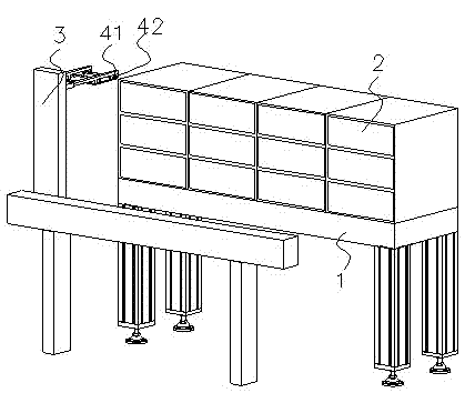
[0042] see figure 1 , as shown in the illustration therein, a circuit board testing system comprising:

[0043] A grid-type cabinet frame 1; the grids are arranged to arrange four horizontally and stack three vertically;

[0044] Twelve box-type testing machines 2 are placed in the twelve grids of the grid-type cabinet frame 1;

[0045] A loading and unloading manipulator 3, used to put the circuit board 4 into the box-type testing machine 2 and take out the circuit board 4 from the box-type testing machine 2;

[0046] A control system includes a PC processor 5 and a PLC control system 6, the box-type testing machine is connected to the PC processor by communication, and the PC processor 5 is connected to the PLC control system 6 by communication, and the The PLC control system 6 communicates with the twelve box-type testing machines 2 and the loading and unloading manipulator 3 respectively.

[0047] A barcode scanning gun 7, the barcode scanning gun 7 scans the barcode of...

Embodiment 2

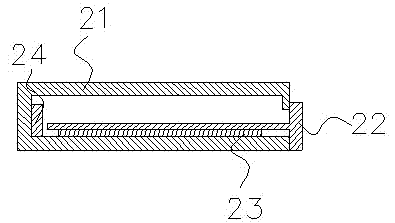
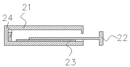
[0080] see Figure 1-Figure 7 , the rest are the same as in the first embodiment, the difference is that the circuit board testing system also includes a material delivery mechanism, and the material delivery mechanism includes:

[0081] A feeding conveyor belt 81, located on the ejecting side of the drawer fixture 22, for transferring the circuit board 41 to be tested;

[0082] A feeding conveyor belt 82 is arranged on the pop-up side of the drawer-type fixture 22, and is used to transfer the tested circuit board 42, and the feeding conveyor belt 82 is arranged above the feeding conveyor belt 81;

[0083] A loading positioning platform 9 is located at one end of the feeding conveyor belt 81 and is located in the same horizontal plane as the drawer fixture 22. The barcode scanning gun 7 is located on the loading positioning platform 9, and the loading The positioning platform 9 includes a platform, a baffle plate arranged on the platform, and a push cylinder arranged relative...

Embodiment 3

[0087] All the other are the same as the embodiment 2, the difference is that the material transmission mechanism includes a plurality of feeding conveyor belts 81, a plurality of unloading conveyor belts 82 and a plurality of back-shaped connection mechanisms, and the multiple feeding conveyor belts 81 pass through The loading and unloading platforms 9 are connected; the plurality of unloading conveyor belts 82 are connected through the loop connection mechanism.


PUM


Abstract

The invention discloses a circuit board testing system, which comprises a test tank, a material taking and putting mechanism and a control system, wherein the control system comprises a PC (personal computer) processor and a PLC (Programmable Logic Controller) control system. A box-type test machine comprises a box body, a drawer-type fixture, a fixture driving component and a test device, wherein one side of the box body is opened; the drawer-type fixture is arranged in the box body in an insertion mode from the opened side of the box body; the fixture driving component is connected with the drawer-type fixture and is used for driving the drawer-type fixture to pop out or retract back to the opened side of the box body; and the test device is arranged in the box body and is communicated with a circuit board to be tested. According to the circuit board testing system, the automation of the circuit board testing system can be realized.

Description

technical field [0001] The invention relates to a circuit board testing system, in particular to a circuit board testing system used for testing the main board of electronic products. Background technique [0002] In the circuit board assembly (PCBA) production line, testing is the link with the weakest degree of automation. For circuit board assembly, everything from brushing solder paste to reflow soldering is completed on the automatic line. Only when it comes to the testing process, its automation At present, on most production lines, testing is done manually by operators. If we observe a production line, we can see that the stations that occupy the most operators are often the test stations. [0003] Analyze the reasons for the low degree of test automation, the main reasons should be: [0004] 1) The test time is very slow compared to the line speed of the product. The cycle time of the test is on the order of one or two minutes, while the line speed is on the order o...

Claims


Application Information

Patent Timeline
Patent Type & Authority Applications(China)
IPC IPC(8): G01R31/28
Inventor 李二文许英南
Owner SUZHOU SIFO SMART AUTOMATION INC CO
Why Eureka
Try Eureka