Eureka AIR delivers breakthrough ideas for toughest innovation challenges, trusted by R&D personnel around the world.

DFT (Design for Testability) method for double-edge trigger

A technology of double-edge triggering and design method, applied in the fields of instruments, computing, special data processing applications, etc., can solve the problems of inability to test vector verification, unable to apply double-edge triggers, unable to handle double-edge triggers, etc., to achieve data processing. The effect of capacity improvement and power consumption reduction by half

Active Publication Date: 2012-12-19
RDA TECH
View PDF2 Cites 12 Cited by
  • Summary
  • Abstract
  • Description
  • Claims
  • Application Information

AI Technical Summary

Problems solved by technology

[0020] The above-mentioned design-for-test method using internal scan design cannot be applied to dual-edge triggers because:
[0021] First, in the second stage of logic synthesis, none of the current mainstream logic synthesis tools in the industry can handle double-edge triggers. Therefore, in the RTL-level circuit description file formed in the first step design input stage, only double-edge flip-flops can be changed. It is a single-edge trigger, so the test of double-edge trigger cannot be carried out according to the existing method
[0022] Its second, the 6th step generates test vector stage, although existing ATPG tool can generate ATPG test vector for double-edge trigger, but because the emulator that ATPG tool comes with can't correctly identify the test model of double-edge trigger, so can't Verify the generated test vectors

Method used


Image

  • DFT (Design for Testability) method for double-edge trigger
  • DFT (Design for Testability) method for double-edge trigger
  • DFT (Design for Testability) method for double-edge trigger

Examples


Embodiment Construction

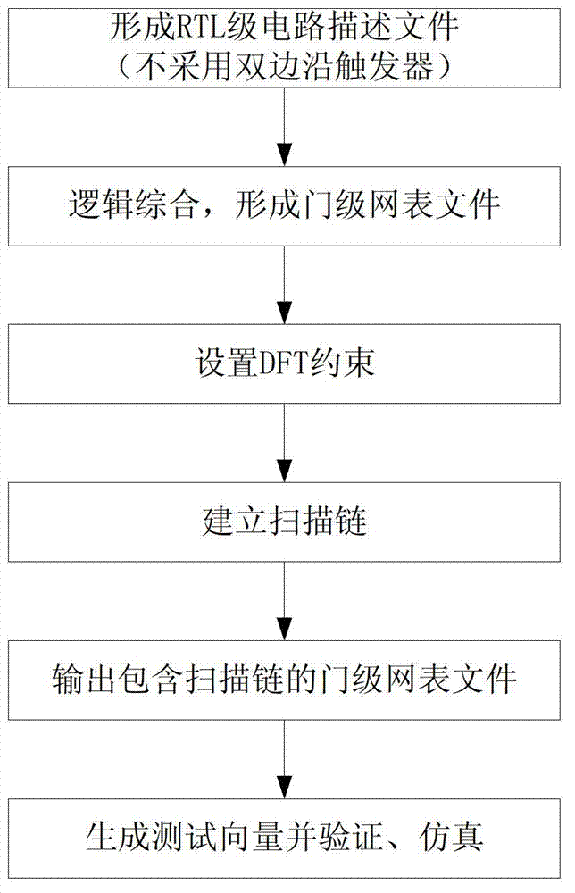
[0047] See Figure 7 , The testability design method used in the double-edge flip-flop in this application also adopts internal scanning design, including the following steps:

[0048] The first step is to design the input to form an RTL-level circuit description file. At this time, double-edge flip-flops are not used. When a flip-flop is needed, all single-edge flip-flops are used. Common design input tool software includes Verilog, VHDL, etc. The suffixes of the RTL-level circuit description files formed by them are .v and .vhd respectively.

[0049] In fact, both of the hardware description languages ​​Verilog and VDHL can be used to describe double-edge flip-flops, but since the subsequent logic synthesis tools do not support double-edge flip-flops, it is not necessary to use dual-edge flip-flops when designing inputs.

[0050] The second step is to logically synthesize the RTL-level circuit description file to form a gate-level netlist file.

[0051] The common logic synthesis t...


PUM


Abstract

The invention discloses a DFT (Design for Testability) method for a double-edge trigger, which comprises the following steps of: on the basis of the existing VLSI (Very Large Scale Integrated) DFT method designed by internal scan, using a double-edge scanning trigger to replace a single-edge scanning trigger in the gate-level netlist file with a built scan chain; adding a test clock circuit; simulating a test vector generated through the scan chain circuit of the single-edge scanning trigger by the scan chain circuit comprising the double-edge scanning trigger; and using the simulated test vector to test the scan chain circuit by an ATE (Automatic Test Equipment) device. In this way, the VLSI DFT method disclosed by the invention can be suitable for the circuit comprising the double-edge trigger and the circuit comprising the single-edge trigger, and further, the method is suitable for popularizing the double-edge trigger in the VLSI design and finally multiplying data handling capacity and reducing half of the power consumption of the integrated circuit.

Description

Technical field [0001] The present application relates to a testability design method of semiconductor integrated circuits, and in particular to a testability design method of semiconductor integrated circuits including double edge triggers. Background technique [0002] The manufacturing of VLSI (Very Large Scale Integrated Circuit) includes hundreds of process flows. In the manufacturing process, slight changes in temperature and environment may cause physical defects in the chip and cause the chip to fail to work properly. [0003] In order to ensure the quality of the factory chips, it is necessary to test and screen the produced chips. VLSI testing is divided into functional testing and structural testing. Functional test is a test for the function realized by the circuit, which should be solved in the design process. The structure test is based on the structure of the circuit (gate type, connection, netlist, etc.) to test the internal signal state through the output pin of ...

Claims


Application Information

Patent Timeline
Patent Type & Authority Applications(China)
IPC IPC(8): G06F17/50
Inventor 郑松魏述然张亮张标谢晓娟
Owner RDA TECH
Why Eureka
Eureka Blog
Learn More