Water treatment project monitoring system based on wireless sensor network
A wireless sensor and monitoring system technology, applied in network topology, wireless communication, comprehensive factory control, etc., can solve the problems of being susceptible to human theft, increasing system maintenance costs, and being easily struck by lightning, reducing costs and development cycles, enhancing Data processing power, flexibility and scalability
- Summary
- Abstract
- Description
- Claims
- Application Information
AI Technical Summary
Problems solved by technology
Method used
Image
Examples
Embodiment 1
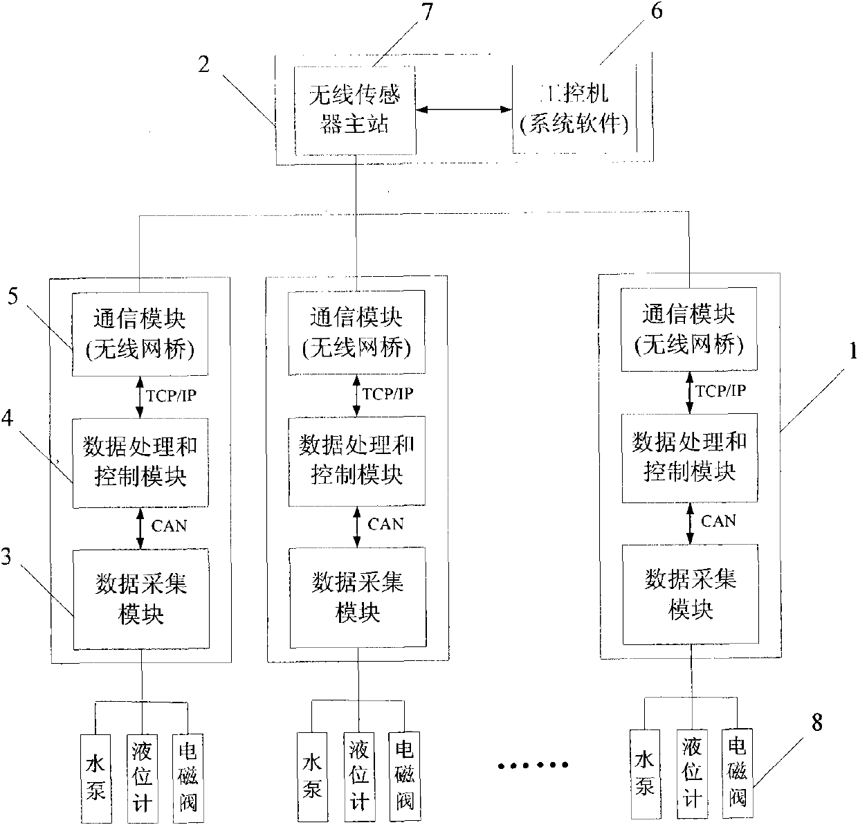
[0019] Such as figure 1 As shown, the monitoring system of the present invention is composed of a wireless sensor network node 1 and a central control system 2 . The wireless sensor network node 1 as a wireless sensor slave station is composed of a data acquisition module 3 , a data processing and control module 4 , and a communication module 5 . Among them, the data acquisition module 3 uses FPGA as the core processor, and has four sub-modules of digital input, digital output, analog input, and analog output, which can realize the acquisition and output of digital and analog quantities, and communicate with the data processing and control module through the CAN bus 4 Communication; the data processing and control module 4 is the main control unit of each node, using the FPGA of the internally customized Nios II soft-core processor as the control core, responsible for controlling each data acquisition sub-board, and collecting real-time status information of the water plant eq...
Embodiment 2
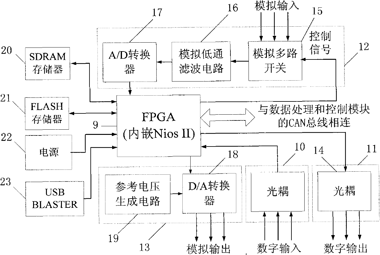
[0021] The structure block diagram of the data acquisition module is as follows: figure 2 As shown, FPGA9 is used as the control core, and the Nios II soft-core processor is customized in it to control each data acquisition sub-module. A data acquisition board includes four data acquisition sub-modules including a digital input module 10 , a digital output module 11 , an analog input module 12 and an analog output module 13 . Among them, the digital input module 10 and the digital output module 11 are relatively simple, and are only composed of optocoupler 14. The addition of optocoupler 14 can realize the isolation of high-voltage equipment and low-voltage equipment, and prevent high-voltage breakdown from damaging low-voltage equipment and mutual interference. The analog input module 12 is mainly used to collect various analog quantities representing the state of the equipment, such as raw water flow, pH value, temperature, turbidity and so on. In order to realize the acqu...
Embodiment 3
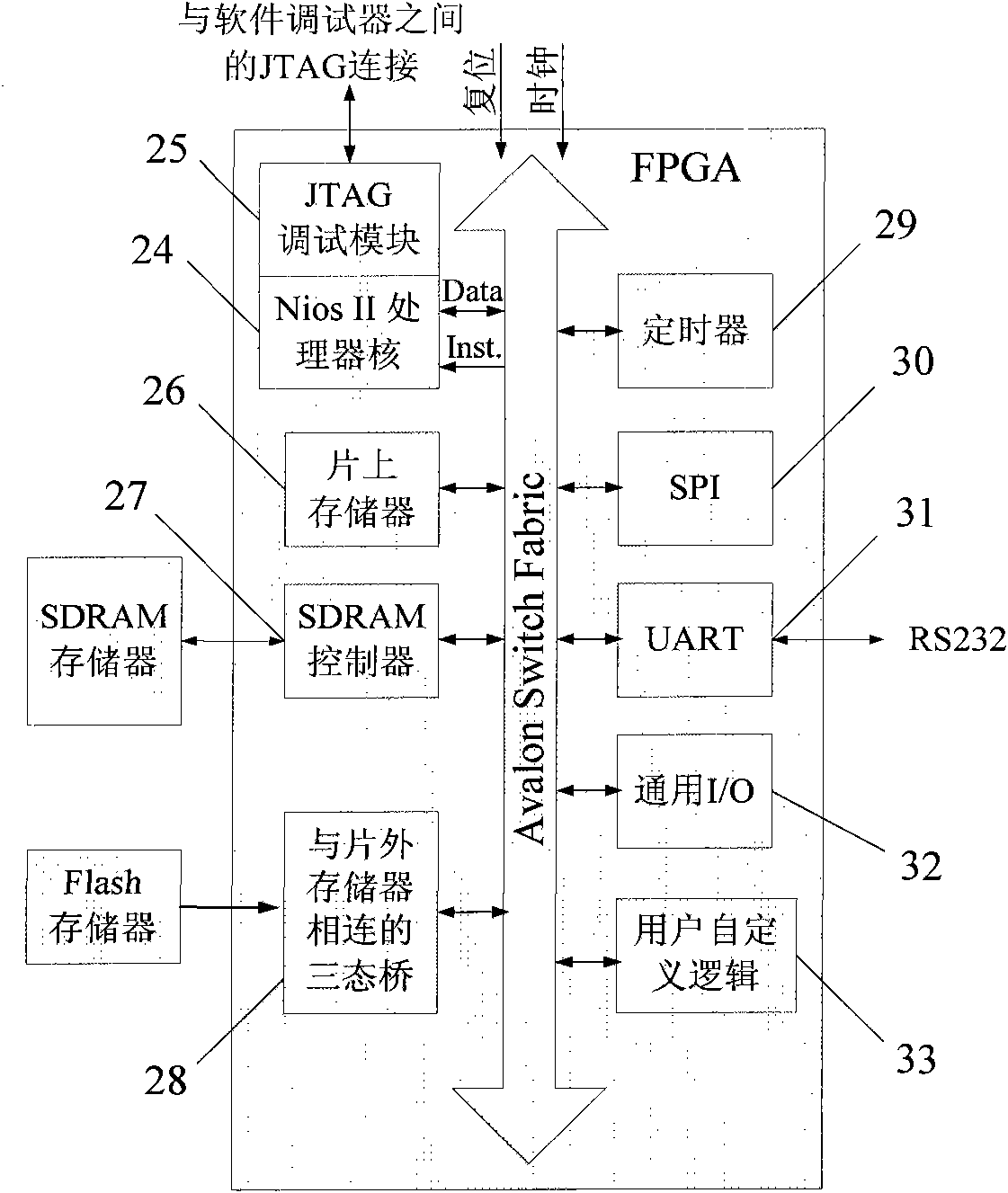
[0023] The overall structural block diagram of the Nios II system is as follows image 3 As shown, the Nios II processor 24 selects the fast NiosII processor for use to achieve faster speed, the JTAG debugging module 25 is used for JTAG connection between the software debugger, and the on-chip memory 26 can be configured as RAM or ROM. Small, running faster, used to debug smaller programs. The SDRAM controller 27 provides an Avalon interface for the FPGA off-chip SDRAM, and processes SDRAM protocol requests. The tri-state bridge 28 connected to the off-chip memory provides a channel for connecting the off-chip memory to the FPGA, and the timer 29 is used as a system clock timer to provide clock interruption. The system adopts two SPI cores 30, one is used to collect the data after AD conversion, and the other is used to control the CAN controller to realize CAN communication. UART31 is used as a common serial communication method for program debugging and data output, and so...
PUM
 Abstract
Description
Claims
Application Information
 - R&D
- Intellectual Property
- Life Sciences
- Materials
- Tech Scout
- Unparalleled Data Quality
- Higher Quality Content
- 60% Fewer Hallucinations
Browse by: Latest US Patents, China's latest patents, Technical Efficacy Thesaurus, Application Domain, Technology Topic, Popular Technical Reports.
© 2025 PatSnap. All rights reserved.Legal|Privacy policy|Modern Slavery Act Transparency Statement|Sitemap|About US| Contact US: help@patsnap.com


