Axial non-uniform air gap hybrid excitation synchronous machine

A mixed excitation synchronous and non-uniform technology, applied to synchronous motors with stationary armatures and rotating magnets, synchronous machine parts, magnetic circuit rotating parts, etc., can solve the problem of increasing the length of the armature winding and its copper loss , low brush and power density, increasing the axial length of the motor, etc., to achieve a wide magnetic field adjustment range, reduce the cost of the motor, and reduce the volume of the motor

Active Publication Date: 2012-12-19
NANJING UNIV OF AERONAUTICS & ASTRONAUTICS
View PDF7 Cites 6 Cited by
  • Summary
  • Abstract
  • Description
  • Claims
  • Application Information

AI Technical Summary

Problems solved by technology

The excitation current of the electric excitation part of the parallel hybrid excitation synchronous motor is usually introduced by the rotor, mostly with a brush structure, and the reliability is poor; there is a large mechanical air gap between the electric excitation part and the permanent magnet part, which is an "ineffective" space, which increases the The axial length of the motor reduces the power density of the motor, but also increases the length of the armature winding and its copper loss
[0005] Based on the above analysis, the present invention proposes a new structural form of hybrid excitation synchronous motor to overcome the shortcomings of the existing magnetic shunt hybrid excitation motor with limited field weakening capability and parallel hybrid excitation synchronous motor with low brush and power density , the case arises from

Method used


Image

  • Axial non-uniform air gap hybrid excitation synchronous machine
  • Axial non-uniform air gap hybrid excitation synchronous machine
  • Axial non-uniform air gap hybrid excitation synchronous machine

Examples


Embodiment Construction

[0024] The technical solutions of the present invention will be described in detail below in conjunction with the accompanying drawings.

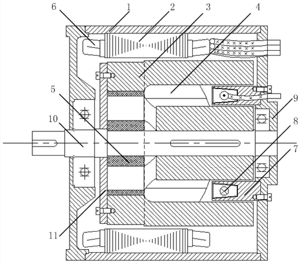
[0025] Such as figure 1 As shown, the present invention provides a hybrid excitation synchronous motor with an axial non-uniform air gap, including a casing 1 and a stator, a rotor, a rotating shaft 10 arranged in the casing 1, and an annular magnetic bridge 7 fixed on the end cover 9 , wherein the stator includes a stator core 2 and an armature winding 6 embedded in the stator slot, and the stator core 2 is fixed on the casing 1 .

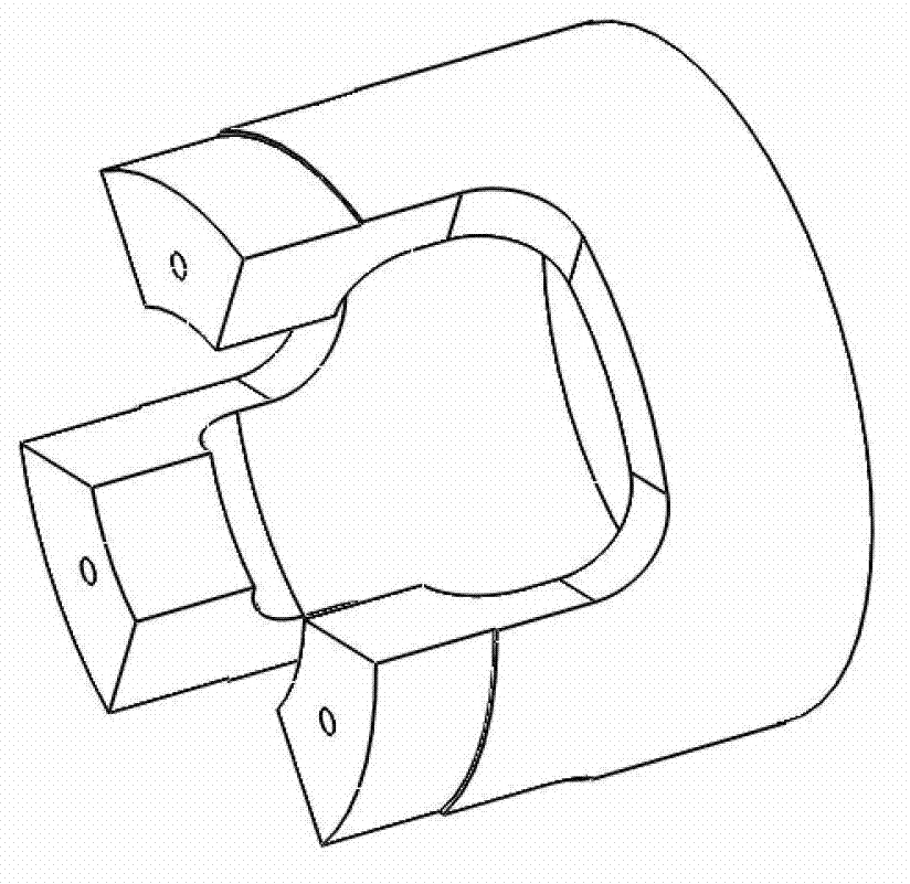
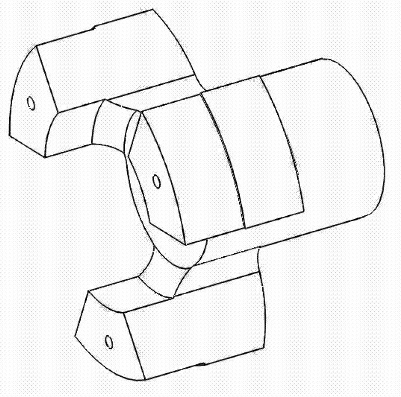
[0026] The rotor is fixed on the rotating shaft 10 and includes rotor N pole shoe 3 , rotor S pole shoe 4 and tangentially magnetized permanent magnet 5 , which will be introduced separately below.

[0027] The part adjacent to the permanent magnet 5 on the rotor N pole shoe 3 and the rotor S pole shoe 4 is called the permanent magnet side, while the rotor N pole shoe 3 and the rotor S pole shoe 4 are not in c...


PUM


Abstract

The invention discloses an axial non-uniform air gap hybrid excitation synchronous machine which comprises a housing, a stator and a rotor which are arranged in the housing, an annular magnetism conducting bridge and a rotating shaft which are fixed on an end cover, wherein the stator comprises a stator iron core and an armature winding embedded in a stator groove; and the rotor is fixed on the rotating shaft and comprises a rotor N pole shoe, a rotor S pole shoe and a tangential magnetization permanent magnet. The axial length of the permanent magnet is less than that of the stator iron core. A rotor N pole and an S pole hole respectively are a permanent magnet side adjacent to the permanent magnet and an electric excitation side which is not adjacent to the permanent magnet, and the lengths of two sections of main gas gaps formed between the rotor permanent magnet side and the stator iron core and between the electric excitation side and the stator iron core are different. The motor is wide in regulating range of the magnetic fields of the air gaps, can realize field weakening control in a wide rotating speed range under a speed regulation state, voltage regulation under a power generation state, and complete field suppression protection under a failure state, and has an important application value in a new energy automobile and an independent source system.

Description

technical field [0001] The invention relates to a hybrid excitation synchronous motor, in particular to an axial non-uniform air gap hybrid excitation synchronous motor. Background technique [0002] The hybrid excitation motor integrates the wide-range adjustable air gap magnetic field of the electric excitation motor and the advantages of high power density and high efficiency of the permanent magnet motor, and has broad application prospects. [0003] The magnetic shunt hybrid excitation synchronous motor can use the extension of the rotor pole piece to provide a bypass path for the permanent magnet flux, so that the motor is in a field-weakening state under normal conditions, and the bypass flux is controlled by the electric excitation magnetic potential in the bypass. Adjustment is carried out to realize the effective adjustment of the air gap magnetic flux. Reasonable design of the stator and rotor structure parameters can obtain a wide range of magnetic field adjustme...

Claims


Application Information

Patent Timeline
IPC IPC(8): H02K21/14H02K21/04H02K1/27
Inventor 张卓然戴冀
Owner NANJING UNIV OF AERONAUTICS & ASTRONAUTICS
Why Eureka
Try Eureka