Digital adjustable micromirror chip on basis of microfluidics and preparation method thereof

A tunable micromirror and microfluidic technology, applied in the field of digital tunable micromirror chip and its preparation based on microfluidics, can solve problems such as insufficient controllability and insufficient zooming accuracy.

Inactive Publication Date: 2012-12-26
PEKING UNIV
View PDF0 Cites 9 Cited by
  • Summary
  • Abstract
  • Description
  • Claims
  • Application Information

AI Technical Summary

Problems solved by technology

However, since this design is highly dependent on the stability of the external pressure source, there will be problems such as the zoom is not accurate enough, and the controllability is not good enough.

Method used


Image

  • Digital adjustable micromirror chip on basis of microfluidics and preparation method thereof
  • Digital adjustable micromirror chip on basis of microfluidics and preparation method thereof
  • Digital adjustable micromirror chip on basis of microfluidics and preparation method thereof

Examples


Embodiment 1

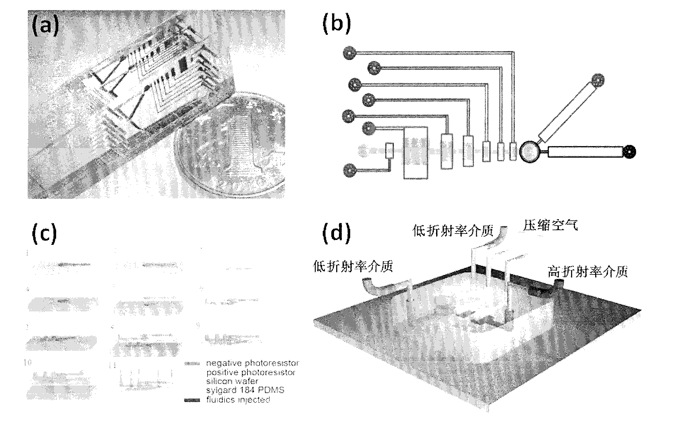
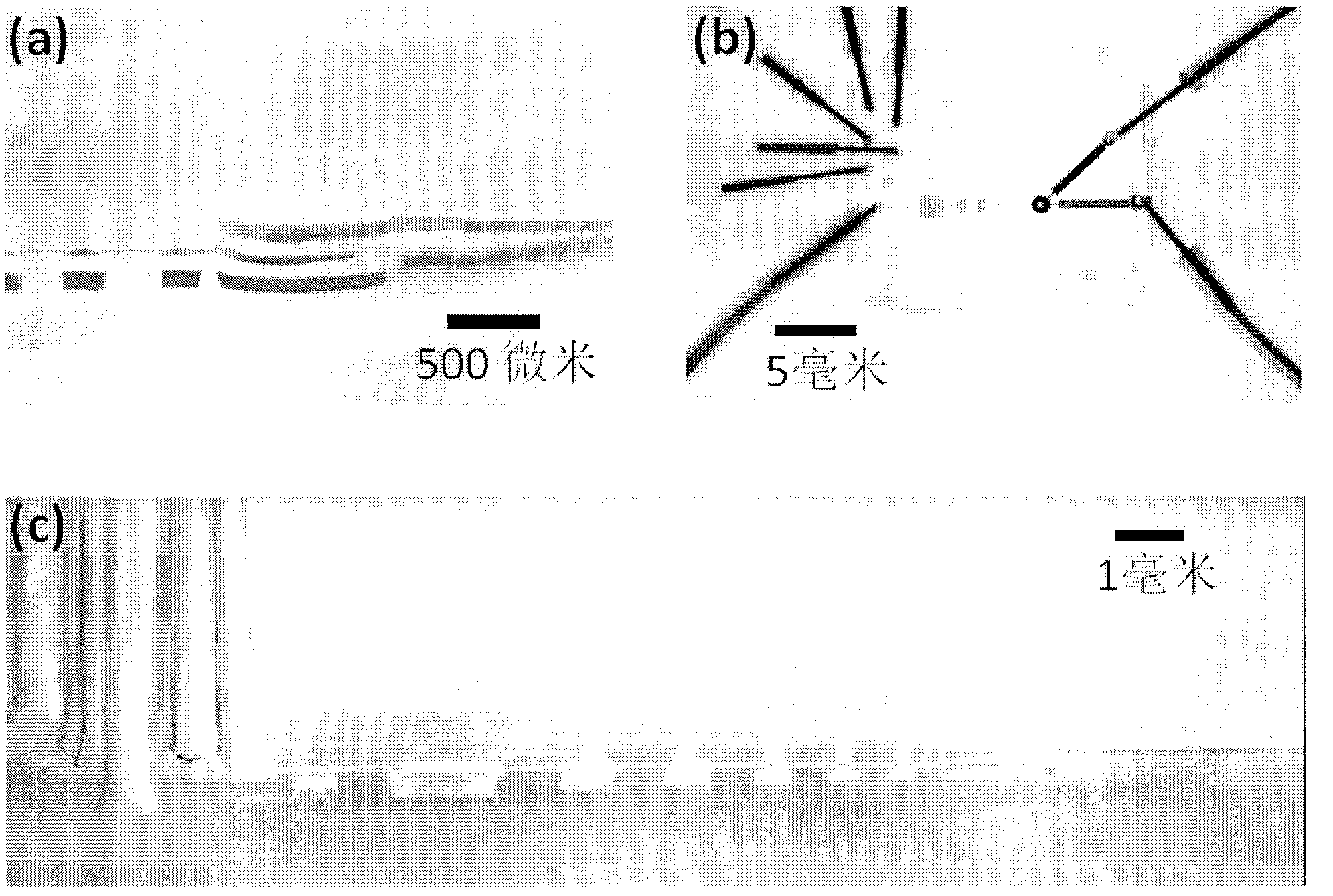
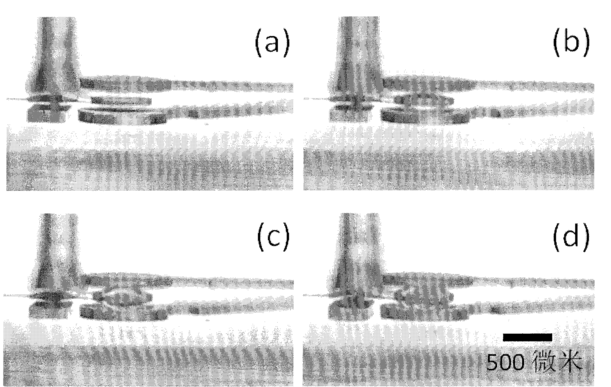
[0024] Composite micromirror chip zoom imaging process.

[0025] For the experimental process and results, see Figure 4 and Figure 5 . exist Figure 4 In a, from 0 to 7, we sequentially pressurize and close 7 control valves, the fluid layer liquid is gradually squeezed into the micromirror at the end of the pipeline, and the two layers of PDMS films above and below the micromirror are pressed to deform and expand to both sides accordingly. Extrude the combination of a biconvex mirror with stepwise change of curvature (focal length) plus two single concave mirrors. Figure 4 b clearly shows the process of digital deformation of this compound mirror group. In the experiment, the top and bottom micromirrors are filled with air, which are negative mirrors with large refractive index difference. Therefore, the two negative refractive index single concave mirrors in the compound mirror group become the core components of magnifying (microscopic) imaging. We used AUTOCAD to d...

Embodiment 2

[0027] Micromirror chip zoom performance.

[0028] Compared with the micromirrors developed based on microfluidic technology in the past, the multilayer composite microgroups we prepared have the characteristics of precise and controllable focal length, fast response speed, and various adjustment methods. At the same time, the design of the three-layer structure has a larger numerical aperture than the traditional single-layer micromirror, and the introduction of a new type of large refractive index difference air concave mirror greatly improves the optical magnification ability of the micromirror. We first set the lateral displacement of the central point of the PDMS film with a step size of 5 microns to simulate the various deformation states of the micromirror (states with different curvatures), and then use the optical calculation software Zemax to calculate the mirror group in each state The focal length, and finally get the change curve of the focal length of the lens gr...


PUM

PropertyMeasurementUnit
diameteraaaaaaaaaa
diameteraaaaaaaaaa
refractive indexaaaaaaaaaa

Abstract

The invention relates to a novel composite structure liquid micromirror with a large zooming ratio. A micromirror chip is made of a transparent flexible material and is provided with three functional layers, i.e. a top layer, a middle layer and a bottom layer; a round microcavity is arranged in each functional layer; the centers of three round microcavities are vertically aligned with one another; each round microcavity is communicated with a pipeline with an inlet; the round microcavity in the middle layer is communicated with at least one liquid storage microcavity arranged in the same layer by a pipeline; pneumatic valves are arranged at the positions in the top layer and/or the bottom layer, which correspond to the liquid storage microcavities; valves of the pneumatic valves are all communicated with the pipeline with the inlet; the inlet is connected with a compressed gas pump; a composite micromirror group mirror with adjustable shape and state is formed by the three round microcavities; and under the action of the digital regulation and control of the valves on a control layer, the focal length of the micromirror can be accurately transformed between centimeters and hundreds of micrometers, so that the controllable large zooming ratio and the micromirror imaging are implemented.

Description

technical field [0001] The invention relates to a micromirror chip and a preparation method thereof, in particular to a digitally adjustable micromirror chip based on microfluidics and a preparation method thereof. Background technique [0002] Optofluidics is a discipline that combines microfluidics with miniature optical components. Today, devices are becoming more and more miniaturized, and various scientific experiments are integrated on a small chip. Optofluidics provides a unique solution for generating, controlling and processing optical signals on a chip platform. For example, in a liquid-core waveguide chip, the liquid in the microfluidic channel is used as the medium for total internal reflection of light, and the optical properties of the waveguide can be modulated simply by replacing the liquid with different refractive indices. As such, microfluidic chips can provide a variety of ways to manipulate the properties of light propagation, especially the focusing an...

Claims


Application Information

Patent Timeline
Patent Type & Authority Applications(China)
IPC IPC(8): G02B26/02G02B3/14G02B21/36G03F7/00
Inventor 黄岩谊费鹏赫滋郑春红陈涛门涌帆
Owner PEKING UNIV
Why Eureka
Try Eureka