Electronic Control Unit

An electronic control unit and terminal technology, applied in electrical components, circuits, electrical solid devices, etc., can solve the problems of MOSFET or transistor temperature rise, increase in manufacturing cost, etc.

Inactive Publication Date: 2012-12-26
DENSO CORP
View PDF7 Cites 6 Cited by
  • Summary
  • Abstract
  • Description
  • Claims
  • Application Information

AI Technical Summary

Problems solved by technology

Therefore, when a large current flows into a MOSFET or transistor for a short time, the temperature of the MOSFET or transistor may rise rapidly
In addition, in the inventions disclosed in Patent Documents 1 and 2, manufacturing costs may increase due to the use of a large amount of grease or the provision of through holes

Method used


Image

  • Electronic Control Unit
  • Electronic Control Unit
  • Electronic Control Unit

Examples


no. 1 example )

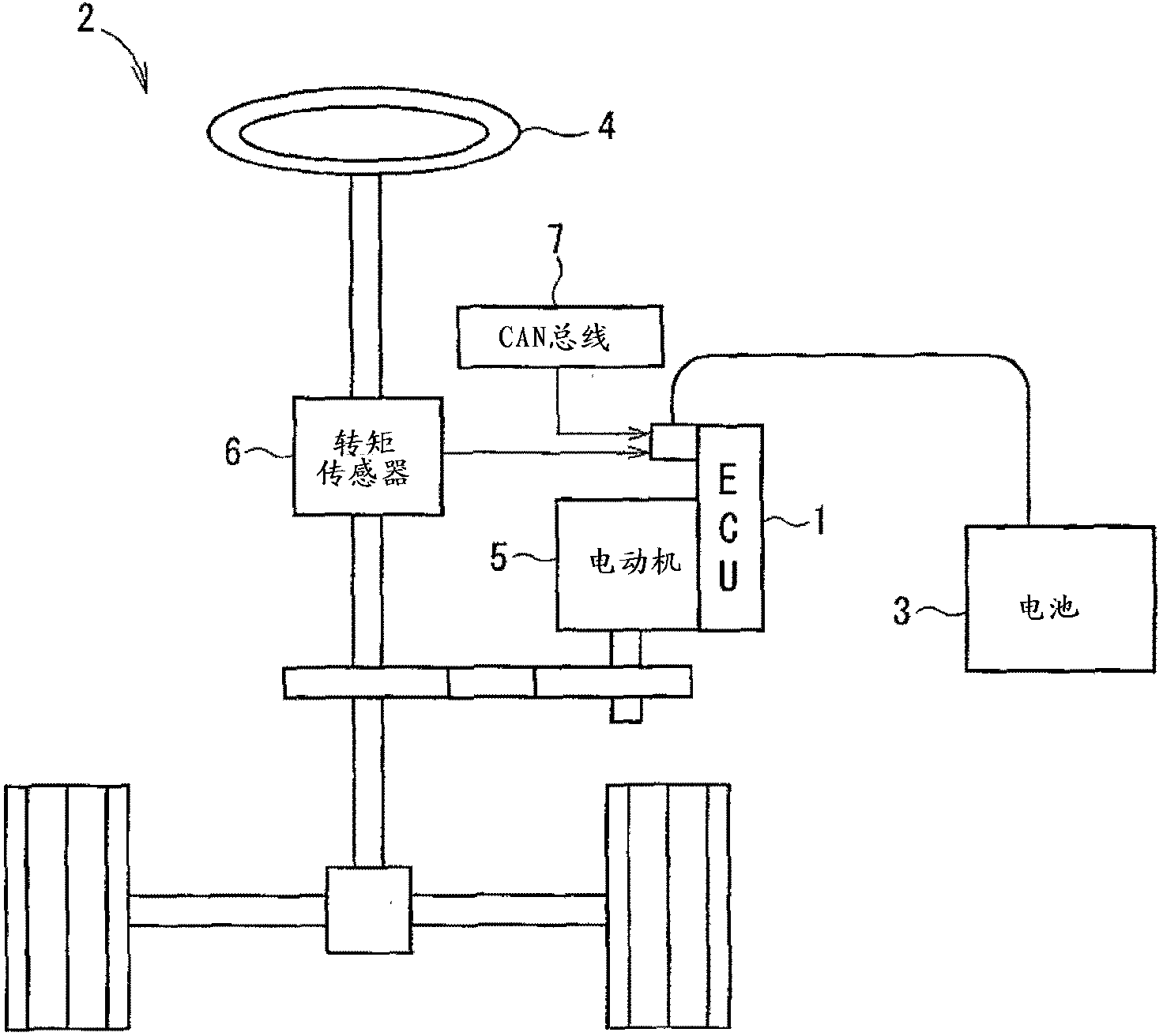
[0036] will refer to Figure 1 to Figure 6 The electronic control unit 1 according to the first embodiment of the present disclosure is described. Such as figure 2 As shown, the electronic control unit 1 can be used in an electric power steering system 2 of a vehicle. The electronic control unit 1 switches the current supplied from the battery 2 to perform drive control of the electric motor 5 for generating an assist force for steering operation to the steering wheel 4 .

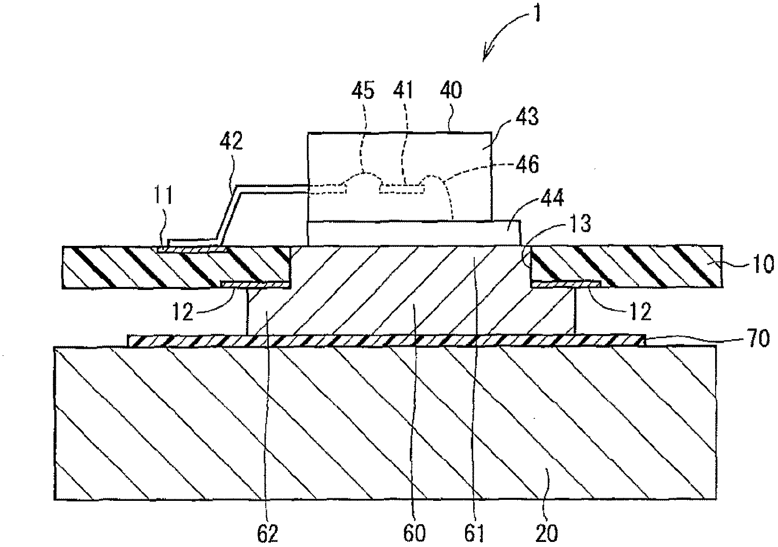
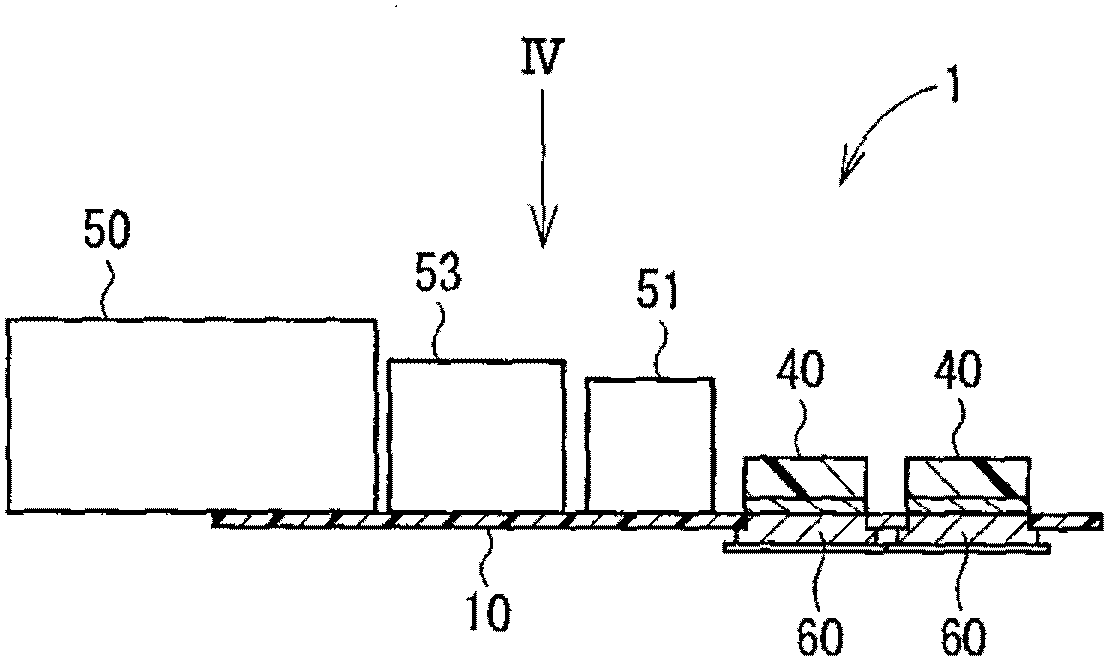
[0037] Such as Figure 3 to Figure 6 As shown, the electronic control unit 1 includes a substrate 10 , a heat sink 20 and a housing 30 . A plurality of electronic components are mounted on the surface of the substrate 10 . The substrate 10 is fixed to a heat sink 20 . The housing 30 is attached to the substrate 10 and the heat sink 20 . The substrate 10 may be a printed wiring board made of FR-4 including glass fiber and epoxy resin. Four MOSFETs 40 are mounted on the surface of the substrate 10 as ...

no. 2 example )

[0051] will refer to Figure 7 to Figure 12 An electronic control unit 1 according to a second embodiment of the present disclosure is described. In this embodiment, components substantially similar to those of the first embodiment described above are denoted by the same reference numerals.

[0052] In this example, if Figure 7 , Figure 8A and Figure 8B As shown, the heat storage body 60 includes a contact portion 63 at each corner of the heat transport portion 62 . The contact portion 63 extends from the heat transport portion 62 toward the substrate 10 . The heat storage body 60 includes an integrated contact part 63 , a heat transfer part 62 and an insertion part 61 . The heat storage body 60 is formed such that the distance H between the end surface of the contact portion 63 facing the substrate 10 and the end surface of the heat transport portion 62 facing the heat sink 20 is precise. In a section parallel to the substrate 10 , the size of the contact portion 63 ...

no. 3 example )

[0056] will refer to Figure 13 An electronic control unit 1 according to a third embodiment of the present disclosure is described. In this embodiment, the area of ​​the surface of the insertion portion 61 facing the heat sink 44 is smaller than the area of ​​the surface of the heat sink 44 facing the insertion portion 61 . The insertion portion 61 and the heat sink 44 are joined to each other by welding. Furthermore, in the present embodiment, when a large current flows into the MOSFET 40 for a short time, the heat sink 44 and the heat storage body 60 store heat, and the temperature rise of the MOSFET 40 can be restricted. When current flows intermittently into the MOSFET 40 for a long time, heat is transferred from the heat storage body 60 to the heat sink 20 via the insulating sheet 70 . Therefore, the temperature rise of MOSFET 40 can be restricted. In the present embodiment, since the area of ​​the surface of the insertion portion 61 facing the heat sink 44 is reduced...


PUM


Abstract

The invention claims an electronic control unit. The electronic control unit comprises a substrate semiconductor module heat storage body insulation and heat sink. The substrate comprises wiring welding area and. The semiconductor module comprises used as switch device of the semiconductor chip and semiconductor chip and wiring is electrically coupled to the terminal sealing semiconductor chip and terminal of the moulded resin and having a moulded resin exposed from the surface and transferring the semiconductor chip at the heat generated by radiating fin. The heat storage body is equipped with the stored in the semiconductor chip is produced by the heat needed by the heat capacity. The heat storage body and the radiating sheet is coupled with. The insulating device is connected with the heat storage body and semiconductor module contact. Heat sink and insulator contact.

Description

technical field [0001] The present disclosure relates to an electronic control unit. Background technique [0002] Conventionally, there is known an electronic control unit that performs drive control of an electric motor used in an electric power steering system (EPS) of a vehicle. The electronic control unit includes metal oxide semiconductor field effect transistors (MOSFETs) and supplies drive current to the motor. In the EPS, when the driver operates the steering wheel during low-speed running of the vehicle or the vehicle is stopped, a large current flows into the MOSFET for a short time, and the MOSFET generates heat for a short time. Therefore, the amount of current that can be applied to the MOSFET in the electronic control unit is limited according to the heat dissipation performance of the MOSFET. In the case where the amount of current that can be applied to a MOSFET in an electronic control unit is limited to, for example, 33 A, the electronic control unit can...

Claims


Application Information

Patent Timeline
IPC IPC(8): H01L23/367B62D5/04
CPCH01L2224/49109H01L23/367B62D5/04H01L2224/48091H01L23/3677H01L2224/48247H01L2924/13091H01L2924/13055H01L2924/12032H01L2924/1305H01L2924/00014H01L2924/00
Inventor 大桥丰斋藤光弘宇於崎裕太
Owner DENSO CORP
Why Eureka
Try Eureka