Eureka AIR delivers breakthrough ideas for toughest innovation challenges, trusted by R&D personnel around the world.

Method for controlling power electronic hybrid system

A technology of power electronics and control methods, applied in active power filtering, AC networks to reduce harmonics/ripples, harmonic reduction devices, etc., can solve poor control accuracy, low control accuracy of PI controllers, and system impact Larger issues

Inactive Publication Date: 2012-12-26
HUNAN UNIV
View PDF0 Cites 14 Cited by
  • Summary
  • Abstract
  • Description
  • Claims
  • Application Information

AI Technical Summary

Problems solved by technology

[0004] 2. Common control methods for active power filters include PI control, hysteresis control, etc.; when PI control is used, the control accuracy is poor, and when the compensation capacity is low, it is easy to oscillate and PI parameters are difficult to adjust; when hysteresis control is used, the ring width setting The setting has a great impact on the system, and the frequency requirement of the switching tube is also high when the ring width is small, resulting in not very wide application
[0005] 3. The control accuracy of the active power filter using the PI controller itself is not high. Once the load changes suddenly and the harmonic situation changes, the filtering effect is particularly unsatisfactory, and online control cannot be realized.
[0006] 4. Static var compensator SVC uses PI controller. Once the reactive load changes, the compensation effect is not ideal, and online control cannot be realized.
[0007] 5. In general fundamental wave resonance injection type active power filter, when its fundamental wave resonance injection branch is applied to high voltage, the fundamental wave resonance part has to withstand very high voltage, the capacity is large, and the cost of engineering application is too high

Method used


Image

  • Method for controlling power electronic hybrid system
  • Method for controlling power electronic hybrid system
  • Method for controlling power electronic hybrid system

Examples


Embodiment Construction

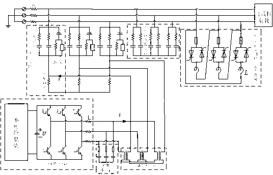
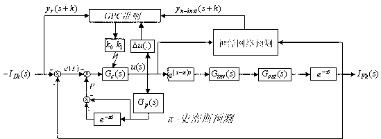
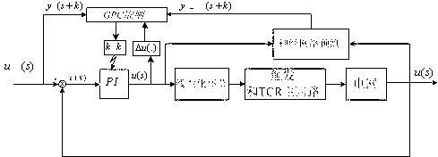
[0029] Such as Figure 1-Figure 3 As shown, the power electronic hybrid control system of the present invention includes an active power filter, a static var compensator, and the static var compensator includes a passive power filter bank and a thyristor-controlled reactor, an active power filter, a passive The source power filter group and the thyristor-controlled reactor are sequentially connected between the grid and the load connected to the grid. The static var compensator SVC is composed of a thyristor-controlled reactor TCR and a passive power filter PPF. The passive power filter PPF consists of several groups of single-tuned filters. The injection active power filter consists of an injection branch and an active power filter, wherein the injection branch includes two sets of single-tuned filters, a set of high-pass filters and a voltage-dividing inductor. This injection branch not only satisfies the smooth injection of the compensation current into the power grid, but...


PUM


Abstract

The invention discloses a method for controlling a power electronic hybrid system. The method comprises a power electronic hybrid control system comprising an active power filter and a static var compensator, wherein the static var compensator comprises a passive power filter group and a thyristor control reactor (TCR); and the active power filter, the passive power filter group and the TCR access between a power grid and loads connected with the power grid in sequence. The passive power filter and the active power filter are used jointly to perform harmonic suppression on high-voltage busbars; and the static var compensator is used to perform reactive compensation, so that delay compensation and online control are realized, control accuracy is enhanced, tracking performance is improved, electric energy loss of the power grid is reduced, and pollution of the power grid is purified.

Description

technical field [0001] The invention relates to a power electronic system, in particular to a control method for a power electronic hybrid system. Background technique [0002] With the continuous development of power electronics technology, there are more and more users with non-linear grid loads and reactive loads, such as rolling mills, electric arc furnaces, electrified railways, etc. The increase of this type of load makes the harmonic components in the power grid more and more serious, causing the loss of power grid components to increase, affecting the normal operation of equipment, and even causing local resonance in the power grid to cause serious accidents; and the increase of reactive load will cause voltage drops, increased loss, etc. Therefore, a pure and high-quality grid environment and power supply quality are expected by both the grid operation department and the load users. However, most of the current products still have many deficiencies: [0003] 1. B...

Claims


Application Information

Patent Timeline
IPC IPC(8): H02J3/01H02J3/18
CPCY02E40/40Y02E40/22Y02E40/20
Inventor 帅智康涂春鸣盘宏斌姚鹏蒋玲戴晓宗楚烺肖凡张杨
Owner HUNAN UNIV
Why Eureka
Eureka Blog
Learn More