Electrical heater and fabricating method thereof, and vehicle

An electric heater and the technology of the manufacturing method are applied in the direction of ohmic resistance heating parts, heating elements, heating/cooling equipment, etc., which can solve the problem of poor heat conduction and heat dissipation, and the heating system is not suitable for defrosting, defogging and heating, and cannot Adapt to problems such as long-term use of automobiles, achieve high heating efficiency, good heat dissipation effect, and good bonding effect

Inactive Publication Date: 2012-12-26
BYD CO LTD
View PDF4 Cites 8 Cited by
  • Summary
  • Abstract
  • Description
  • Claims
  • Application Information

AI Technical Summary

Problems solved by technology

[0005] The technical problem to be solved by the present invention is that the existing heating system for fuel vehicles is not suitable for defrosting, defogging and heating in electric vehicles and hybrid vehicles, while the existing heating systems for ele

Method used


Image

  • Electrical heater and fabricating method thereof, and vehicle
  • Electrical heater and fabricating method thereof, and vehicle
  • Electrical heater and fabricating method thereof, and vehicle

Examples


Example Embodiment

[0037] Example 1

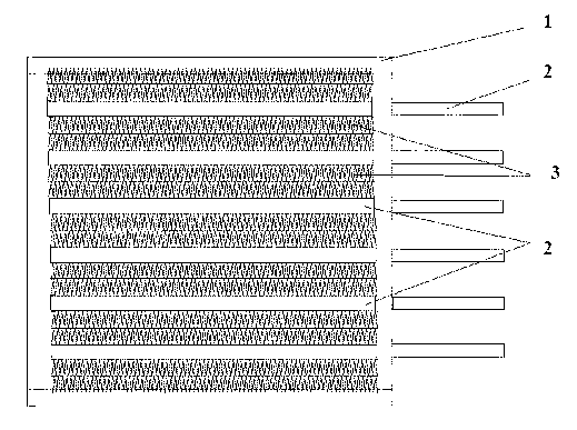
[0038] This embodiment combines figure 1 To illustrate the production of the electric heater of the present invention:

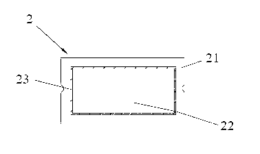
[0039] Step 1. Provide a square frame, 7 corrugated aluminum heat sinks, and provide 6 aluminum square passes and multiple PTC thermistors, and install the multiple PTC thermistors on the 6 respectively 6 heating elements are formed in the aluminum square pass;

[0040] Step 2. Use a sandblasting process to perform sandblasting on the surface of the aluminum square tube connected to the heat sink to form a first sandblasting surface; the sandblasting process uses compressed air as the power to spray the spray material onto the surface to be processed at a high speed , The pressure of the compressed air is 4Kg / m 2 , The blasting material uses quartz sand, the particle size of the quartz sand is 40 microns, the purity is higher than 99.5%, and the flow rate of the quartz sand is 1.0m 3 / min;

[0041] Step 3. The 6 heating elements and the 14 heat ...

Example Embodiment

[0042] Example 2

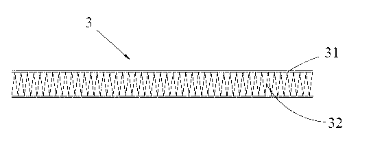
[0043] The manufacturing method of the electric heater of Example 2 is basically the same as that of Example 1, the difference is: Step 2 also includes using a sandblasting process to perform sandblasting on the surface of the heat sink for connection with the aluminum square to form a second sandblasting Surface; Step 3 is set between the first sandblasting surface of the aluminum square pass and the second sandblasting surface of the adjacent heat sink, and the electric heater A2 is produced by the manufacturing method of Example 2.

Example Embodiment

[0044] Example 3

[0045] The manufacturing method of the electric heater of embodiment 3 is basically the same as that of embodiment 1, the difference is: the number of corrugated aluminum heat sinks provided in step 1 is 7, and the number of adjacent heating elements in step 3 A heat dissipation bar is set, and a heat dissipation bar is set between the outermost heating element and the frame, and the electric heater A3 is manufactured by the manufacturing method of Example 3.


PUM

PropertyMeasurementUnit
Surface roughnessaaaaaaaaaa

Abstract

The invention provides an electrical heater, comprising a frame, wherein multiple heat sink strips and multiple heating elements are arranged in the frame side by side, multiple heat sink strips and multiple heating elements are arranged at intervals, multiple heating elements comprise aluminum square tubes and PTC (positive temperature coefficient) thermistors installed in the aluminum square tubes, the aluminum square tubes are used for forming a first sandblasted surface with the surface which is connected with the heat sink strips, a thermal conductivity silica gel is arranged between the first sandblasted surface of the aluminum square tube and the adjacent heat sink strip, the aluminum square tube and the heat sink strips are bonded together by the thermal conductivity silica gel. The invention also provides a method for fabricating the electrical heater. The electrical heater has strong bond strength and good bond effect between the aluminum square tube and the adjacent heat sink strip, so that the heat conducting performance between the heating elements and the heat sink strips is excellent, the heat dissipation effect of the heat sink strips is good, and the frost removing, mist removing and heating effect are not affected even when the vehicle is used under the bumpy road condition for a long term.

Description

technical field [0001] The invention relates to the field of heaters, more specifically, to an electric heater, a manufacturing method thereof, and an automobile. Background technique [0002] In fuel vehicles, the defrosting and heating of the car in winter use an independent heat source (fuel) heating system or a waste heat (using engine cooling water or waste heat of exhaust gas) heating system. These two kinds of car heating and heating systems all need to rely on the engine of the car, that is to say, the defrosting, defogging and heating in the car can only be implemented when the engine is working. Heating is also impossible. In addition, the heating efficiency of this heating system is very low, and its structure is relatively complicated. It takes 6-10 minutes to supply heat after starting the engine in winter, especially for defrosting. The defrosting of the front windshield of the car requires the engine to work for a period of time. The heat can only be supplie...

Claims


Application Information

Patent Timeline
IPC IPC(8): H05B3/06B60H1/22
Inventor 任茂林邱红梅李晓芳林信平
Owner BYD CO LTD
Why Eureka
Try Eureka